background image

Control System Overview

19

9  Control System Overview

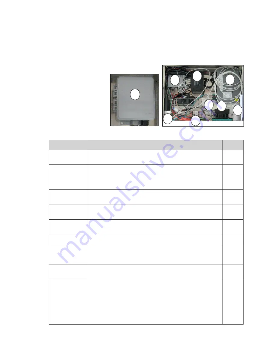
DB-65 series control components are enclosed in the display.

Fully Embedded Control System

DB-65 series billboards have two major components. The ISP enclosure, located behind 

the third door from the right; and the SmartLink

TM

mounted inside the first 

or second door from 

the right. Display back 

sheets are labeled with 

component locations to 

make finding components 

easy. The table below 

describes each control 

system. Refer to 

Figure 34


and 

Figure 35

 and the 

component descriptions 

below.

Component

Function

Number

Thermostat

Measures the temperatures inside the ISP enclosure and turns on 

the fan or the heater as needed. 

1

Fan/Heater

Since ISP equipment is affected by lower temperatures, a heater 

prevents the ISP enclosure from going below a functional range.

High heat can damage some electronics, the fan cools the ISP 

enclosure to keep the equipment in a safe functional range.

2

Laptop and Cell

Phone Location

Can be used to charge laptop or cell phones. Do not plug drills or 

other power tools into this outlet.

3

Door Switch

Detects if the ISP enclosure door is open. If opened, an alert is 

created and the content switches to predetermined content. 

4

POE Ethernet

Switch

Connects network devices and provides webcam power.

5

Z-Filter

Suppresses electrical noise in the electrical line.

6

VIP-5160

Converts DMP-8000 content to a format recognized by the display 

and sends the signal to the PLRs in the display. The VIP-5160 also 

gathers diagnostic data from the display and sends it to IDM.

7

DMP-8000

Converts content data from the content management server into 

a format recognized by the VIP and sends it out to the VIP-5160.

8

SmartLink

TM

Remote power reboot device. Four relays control the following 

components: 

•  Relay 1 - ISP equipment

•  Relay 2 - DMP-8000 and VIP-5160

•  Relay 3 - Display

•  Relay 4 - Auxiliary components

Note: 

Do not cycle relays on site. Call the help desk to cycle 

relays.

9

9

Figure 34: 

SmartLink

TM

1

2

3

4

5

6

7

8

Figure 35: 

ISP Enclosure

Содержание 65 Series

Страница 1: ...201 Daktronics Drive Brookings SD 57006 5128 www daktronics com support 800 325 8766 65 SERIES DIGITAL BILLBOARD INSTALLATION MANUAL P2210 DD4294926 Rev 01 14 February 2020...

Страница 2: ...limits for a Class A digital device pursuant to part 15 of the FCC Rules These limits are designed to provide reasonable protection against harmful interference when the equipment is operated in a com...

Страница 3: ...ion Light Sensor Relocation 12 6 Webcam Mounting 13 Mount the Webcam to the Arm 13 Standard 10 Foot Fixed Webcam Arm Installation 13 Standard 10 20 Foot Adjustable Length Webcam Arm Installation 14 In...

Страница 4: ...This page intentionally left blank...

Страница 5: ...ys Important Contact Information Daktronics Help Desk 1 877 DAK HELP 325 4357 Display Identification This section provides information that is helpful in understanding a Daktronics digital billboard d...

Страница 6: ...econd row from the bottom Spare parts box is removable to allow for rear service access Modules module tool and splice tool for sectional displays are included Other standard service tools are not inc...

Страница 7: ...sing a module latch assembly and a louver Each module is individually removable from either the front or back of the display Module part numbers vary by pixel pitch ProLink Router PLR The PLR takes da...

Страница 8: ...k Customer must provide until final proof of performance Crane Cordless drill Drill bits Hammers Ladder 6 8 10 Laptop Pry bar Ratchet tie downs come along Socket and open end wrench 11 16 Socket exten...

Страница 9: ...installed prior to lifting the display to the head For ledger bracket details refer to DWG 988359 use with offset mounts and DWG 3041598 use without offset mounts in Section A Reference Drawings p 23...

Страница 10: ...pare parts rack in the bottom left end bay when viewed from the back and verify all installation tools and installation hardware were sent with the display Contact the Project Manager immediately if m...

Страница 11: ...is two sections wide and has a vertical splice either from the factory or on site locate the horizontal splice tube at the splice location This tube is shipped installed and must be secured before lif...

Страница 12: ...opening Refer to Figure 6 19 Tighten all of the nuts on the rocker clamps or offset extrusion bolts to 75 ft lbs with an impact wrench and the torque stick 20 Place and tighten all remaining mounting...

Страница 13: ...splice channel 5 Starting at one end of the display insert the top lip of the splice wrench into the top section mounting channel Refer to Figure 12 6 Rest the bottom lip of the splice wrench against...

Страница 14: ...f the display in place Refer to Figure 15 14 Slide the vertical splice tube so it is split evenly between the top and bottom display sections 15 Tighten the vertical splice tube nuts to secure the spl...

Страница 15: ...section term panel 21 Connect the signal splice cables from the display top section a Signal A on the top section PLR to Signal B on the bottom section PLR b Signal B on the top section PLR to Signal...

Страница 16: ...d to the MDLS mounting arm 8 Place the MDLS assembly on the MDLS mounting arm 9 Use the attachment bolts and nuts to secure the MDLS assembly to the mounting arm 10 Use tek screws to secure the MDLS m...

Страница 17: ...nstallation Standard 10 foot fixed webcam arms are used on display less than or equal to 10 modules high and less than or equal to 33 modules wide 1 The webcam arm ships with all hardware and arm comp...

Страница 18: ...splay back Refer to Figure 24 4 Slide the two remaining channels into the vertical mounting channel on the display back 5 Place the bolting template over the bolts in the channel The bolting template...

Страница 19: ...wer and starting the display call Daktronics NOC and have a technician verify they can detect the video server If the video server is not detected ensure the power and signal cables are securely attac...

Страница 20: ...iagram for site required power 2 Run conduit from the main distribution panel provided by customer to the display power entrance s 3 Route power to the display through a disconnect switch 4 Loosen the...

Страница 21: ...resistance Daktronics is not responsible for improper grounding or damage incurred as a result of improper grounding Grounding methods must meet the provisions of all applicable local and national co...

Страница 22: ...ack are Modules ISP Enclosure Filters Splice Wrench Hex Head Wrench 1 8 L and T Handle Torx Bit T 20 Power Supply Spare Parts Location Doors Control System Location Support Ledger Ventilation Exhaust...

Страница 23: ...pment in a safe functional range 2 Laptop and Cell Phone Location Can be used to charge laptop or cell phones Do not plug drills or other power tools into this outlet 3 Door Switch Detects if the ISP...

Страница 24: ...ips screw driver to loosen the screws holding the ISP door on and lift the door off Refer to Figure 36 3 Ensure ISP door and screws are secured after service to guarantee proper function of the door s...

Страница 25: ...he structure base 6 Verify the status lights on the surge suppressor are on 7 Check the LED indicators on the equipment in the ISP enclosure to ensure they are on 8 Ensure the DMP 8000 and VIP 5160 LE...

Страница 26: ...ay Image Quality After the display is showing content visually inspect the display for Inaccurate or off color Module edges The display is too dim or bright Modules out Incorrect content transition Mo...

Страница 27: ...1286 Billboard Pivoting 10 15 Webcam Arm DWG 1065544 Billboard Fixed 10 Webcam Arm 2 Point Mount DWG 1067554 Billboard Fixed 10 15 Webcam Arm 4 Point Mount DWG 1142216 Billboard Fixed 20 Webcam Arm 4...

Страница 28: ...This page intentionally left blank...

Страница 29: ...Daktronics Warranty and Limitation of Liability 25 B Daktronics Warranty and Limitation of Liability Click here to view Warranty and Limitation of Liability SL 02374 information...

Отзывы: