background image


MAN#650333:B 


FLTR (ROAD GLIDE)  
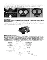
You will need to remove the speedometer and tachometer instrument bezel.  To do this, remove two small screws on 
the left and right side of the bezel.  Lift up on the back of the bezel and slide the tab that is under the ignition switch out 
from under the switch cover (see Photo A below).  Unplug the gauge connections and unplug the indicator lights so the 
bezel can be completely removed for easier installation of the new gauge.  Remove the clamp that holds the 
speedometer to the bezel and remove the gauge and gasket.   


Photo A                   


 Bezel removed                         Gauges/Grommets removed 


IMPORTANT NOTE! 
SAVE ALL CLAMPS, GASKETS, and SCREWS FROM THE STEPS ABOVE AS THEY WILL BE USED TO SECURE THE NEW 
DAKOTA DIGITAL GAUGE 

Next you are ready to install the new gauge into the fairing. Install the gauge and secure using the original hardware 
that was removed: clamp, gasket, and screws. Be sure the alignment tab on the clamp lines up with the notches in the 
fairing.  Some fairings may only have one notch, line up at least one tab on the clamp with the notch in the fairing, this 
will ensure the gauge is centered and aligned correctly.   


WIRING (plug in connections) 

Plug the original speed connector directly into the new gauge. The BLUE wire on the small, two-wire plug controls the 
dimming circuit. When this wire re12 volts, the gauge will dim to 50% intensity. This wire can be connected to a 
toggle switch, or to a Dakota Digital MCL-36K-TCH (the tachometer has a sensor that activates the dimming feature 
when ambient light is low).  The GREEN wire can provide a switch signal to allow other Dakota Digital MCL-3K gauges 
to be set up from the factory switch on the dash.  The GREEN wire will not be used if the speedometer is the only 
gauge being replaced. 


Содержание MCL-36K-SPD

Страница 1: ...odel to model so please follow the service manual to expose the wiring and gauges Don t be alarmed by the amount of wires behind the fairing this is a direct plug in gauge and these detailed instructions will guide you through it Street Glide with outer fairing removed Road Glide with outer fairing removed REMOVAL OF FACTORY GAUGE ULTRA FLHT FLHX STREET GLIDE batwing fairings Unplug the speedomete...

Страница 2: ...he fairing Install the gauge and secure using the original hardware that was removed clamp gasket and screws Be sure the alignment tab on the clamp lines up with the notches in the fairing Some fairings may only have one notch line up at least one tab on the clamp with the notch in the fairing this will ensure the gauge is centered and aligned correctly WIRING plug in connections Plug the original...

Страница 3: ... you are only installing one or a couple Dakota Digital MCL 3K gauges then setup may seem a little strange since they are designed to work as a set The first step in the setup procedure is to select which gauge you are going to adjust Each gauge will either show a number or a label If the gauge is showing a label then that gauge will be selected to enter setup All of the other gauges will exit set...

Страница 4: ...peedometer is calibrated by the engine computer but the speedometer reading can be adjusted through the gauge The adjustment is set a value from 0 75 75 1 25 125 with 1 00 being no change Press and release the switch until AdJvSt is displayed then press and hold the switch until is displayed Release the switch The display will show SLoWJ or FASTER Slow will make the speedometer read lower faster w...

Страница 5: ...culated distance to empty This will count down making adjustments as necessary until the range is 35 miles 56km or less and then it will show r Lo The gauge will continue to make adjustments to match your driving habits with each fill up After the initial setup you are not required to wait for the fuel to get below tank before refilling Press and release the switch until RANGE is displayed then pr...

Страница 6: ... wire harness is getting power all Check wiring connections Blue wire should have 0 volts times all of the time when tachometer is bright Security indicator does Loose or incorrect connection to indicator wire Check that the appropriate indicator wire has about 0 volts not work when the indicator should be off and about 12 volts when the indicator should be on Engine indicator does No data from EC...

Отзывы: