


Page 26 of 58
SK2019 FMCD-V-ECM-001
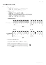
Configuration Settings
There are 2 DIP switches set on the PCB
1.
DIPA-S1 (8 positions)
•
SW1
–
SW6: used for master-slave / BMS network address.
•
SW7
–
SW8: used for operating mode configuration.
2.
DIPB-S2 (6 positions)
•
SW1: Occupancy / economy mode selection.
•
SW2: 2-pipe / 4-pipe configuration selection.
•
SW3: Thermoelectric valve configuration selection (2-pipe system only).
•
SW4: Pre-heat protection temperature selection.
•
SW5
–
SW6: brushless DC fan motor configuration.
Default DIP Switch Settings
Figure 1
DIPA
–
S1
DIPB
–
S2
Figure 2
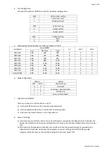
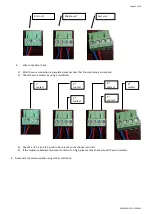
3.
Thermoelectric Valve Configuration
On board DIP switch SW3 of DIPB is used for this configuration.
SW3
Thermoelectric valve (MTV)
1
With valve
0
No valve
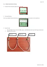
Unit Configuration
WITHOUT Valve
Unit Configuration
WITH Valve
0=OFF
1=ON