


Page 24 of 59
Page 24 of 58
SK2019 FMCD-V-ECM-001
Abbreviations
Ts = Setting temperature
AUX1 = Hot water free contact
Tr = Room air temperature
AUX2 = Chilled water free contact
Ti1 = Chilled water coil temperature
MTV1 = Chilled Motorized valve
Ti2 = Hot water coil temperature
MTV2 = Hot Motorized valve
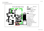
I/O Port Definitions
I/O
Code
2-Pipe
4-Pipe
Analogue
Input
Return air sensor
AI1
Return air temperature (Tr)
2-pipe coil circuit sensor
AI2
Chilled / hot water coil circuit (Ti1)
Chilled water coil circuit (Ti1)
Hot water sensor
AI3
N/A
Hot water coil circuit (Ti2)
Input
LED display / IR receiver
X-DIS1
Digital communication port to LED display / IR receiver board.
Wired wall pad
TTL1
Digital communication port to wired wall pad board.
Digital input
Occupancy contact
On/Off
Window contacts: for remote ON/OFF (when DIPB SW1 = 1).
Economy contacts: for remote activation of economy mode (when DIPB
SW1 = 0).
Electrical heater safety
switch
EH
Voltage-free (NC). The contact is closed before the EH is turned on.
Power input
Phase
L1
Power supply to the PCB and all the loads connected to the voltage
outputs.
Neutral
N1
Power supply to the PCB and all the loads connected to the voltage
outputs.
Earth
PE1
Power supply to the PCB and all the loads connected to the voltage
outputs.
Voltage
output
Fan
CN4
Fan driver
Valve 1
MTV1
2-pipe coil circuit valve output
–
chilled / hot water valve.
Voltage output (L)
4-pipe coil circuit valve output
–
chilled water valve.
Voltage output (L)
Valve 2
MTV2
Reserved
4-pipe coil circuit valve output
–
hot water valve.
Voltage output (L)
Voltage of electrical
heater (Live)
HEAT
Voltage output (L), maximum 25 A
Output
Stepping motor
CN1 /
CN2
Louver stepping motor relay
Auxiliary contact 2
AUX2
Cooling mode signal relay (NO). Voltage free contact.
Auxiliary contact 1
AUX1
Heating mode signal switch (NO). Voltage free contact.
Serial BUS port
CN3
Master-slave network serial connection OR
MODBUS / local PC host network serial connection.