


Page 25 of 58
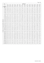
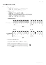
SK2019 FMCD-V-ECM-001
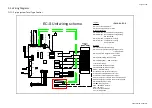
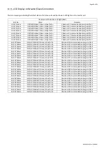
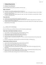
Wiring Diagrams
2-pipe system Total Type Control
R
es
et
s
w
itc
h
fo
r S
W
C
-2
0,
2
4,
3
0
Lo
uv
er
S
te
pp
in
g
m
ot
or
CN1
D
ip s
w
itc
h A
N
L
KEY
N
L
V1
V2
VALVE1
HEAT
VALVE2
AUX1
AUX2
FUSE
D
ip s
w
itc
h B
Wired Wall
pad plug
A
B
A
B
Yellow/Green
R
es
et
s
w
itc
h
SW
C
06
~1
8
CN4
Plug
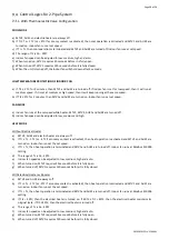
Legend:
DIPA-S1
SW1-5: set the unit address
SW6: set unit type: master or slave
Mode Configuration
SW7=0;SW8=0; unit operates in cooling/heating;
SW7=0;SW8=1; unit operates in cooling/heating
with booster EH;
SW7=1;SW8=0 ; unit operates in cooling
SW7=1;SW8=1; unit operates in cooling
with primary EH
DIPB-S2
SW1:Occupancy connect setting
SW2: Unit configuration setting: 0=2pipe system;
1=4-pipe system;
SW3: on/off valve configuration:0= no valve
1=with valve
SW4:preheat setting: 0=36C; 1=28C
SW5,SW6,S3(jump)----RPM selection.
L\N----Power supply
VALVE1:230V on/off valve output;
VALVE2:230V on/off valve output;
HEAT----Electrical heater
AI1:Return air temperature sensor(Tr) ;
AI2:Indoor coil temperature sensor1 (Ti1) ;
AI3:Indoor coil temoeraturesensor 2 (Ti2) ;
AUX1:Voltage free contact; ON:unit in heating mode.
AUX2:Voltage free contact; ON:unit in cooling mode.
ON/OFF:Occupancy contact
CN1 2---Stepping motor
CN3---Serial BUS contacts.
CN4---Ec motor
DIS---Led receiver display
TTL---wired wall pad
CPU
S4 S3
AI3 AI2 AI1
CN2
prog
EH
DIS
TTL1
S1
S2
CN3
ON/OFF
TERMINAL
{
ch
ille
d /
ho
t w
ate
r
4-p
ipe
co
il c
irc
ut
se
ns
or
2 p
ipe
se
ns
or
(T
i1)
R
en
tu
rn
se
ns
or
(T
r)
(T
i2)
:h
ot
w
ate
r
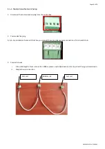
EC-S Unit wiring scheme
EH
B A
R
S4
85
p
lug
A
1
A
1
A
2
A
2
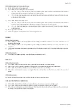
Auxiliary heating contact
Auxiliary cooling contact
Electrical heater
FUSE
EC moter
DISPLAY
PROs
PR
O
co
nta
ct
110C
IPA19-DL-EC-S