34
D004-000017
Supply Power Connection (100-240VAC)
4123 Series User Manual
Step 6)
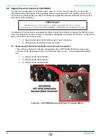
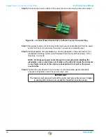
Connect power source cable to the power source connector plug removed in step 3.
Figure 36 — Connect Power Source Cable to Power Source Connector Plug
Step 7)
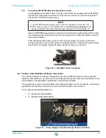
Plug power source connector plug (with power source cable attached) into the power
source terminal in the enclosure (See step 3 removal and related figures).
Step 8)
Install glandplate onto glandplate box. Secure glandplate in place with sixteen (16)
glandplate hold-down screws (6-32 Stainless Steel, Pan Head Torx Screws, 3/8”L)
(See step 1 removal).
NOTE: Carefully pull power cable through the cord grip while installing the
glandplate. Leave a small amount of slack on the cable for inside the enclosure
so any future removal of the enclosure back plate will not pull on the power
source cable.
Step 9)
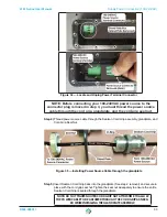
Tighten the outer Sealcon Cord Grip cap nut until the sealing gasket completely
encases and tightens around the power source cord.
IMPORTANT
The internal cord grip seal nut and the outer cord grip cable cap are integral
in sealing the enclosure as needed for hazardous location usage.


