Dairymaster MOOMONITOR + Скачать руководство пользователя страница 18


4-11 

INM12006 – MOOM V3.0 


Copyright Dairymaster 2015


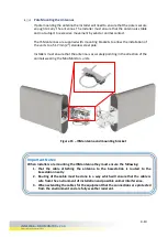
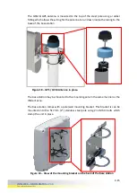
Once the holes are drilled secure each bracket to the masonry structure using 2no 
M10 X 70mm coach screws with a suitable wall plug. 


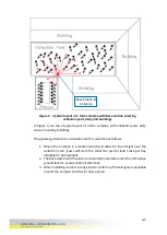
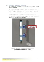
Figure 12 – Mounting kit for base station onto a masonry wall 

(Base station and antenna removed for clarity) 

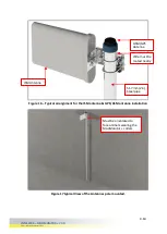
Figure 13 – Basestation mounted using the wall mounting kit. 

Содержание MOOMONITOR +

Страница 1: ......

Страница 2: ...tions only 5 12 Basestation LED Power up 5 14 6 Controls 6 15 Configuring the base station using a USB to UART connection 6 15 Configuring the base station using a UART connection 6 16 6 1 2 1 Step 1...

Страница 3: ...mal Tables 6 56 6 3 3 2 Draft Table 6 57 View Cow data 6 58 Adding Events 6 60 6 3 5 1 Add Heat 6 61 6 3 5 2 Add Insemination event 6 62 6 3 5 3 Add Drafting Event 6 63 6 3 5 4 Adding Calving event 6...

Страница 4: ...6 4 6 1 Add Health Event 6 91 6 4 6 2 Add Heat Event 6 92 6 4 6 3 Add Insemination 6 93 6 4 6 4 Add Embryo Transfer 6 94 6 4 6 5 Add Pregnancy Check Result 6 95 6 4 6 6 Add Dried Off Event 6 96 6 4 6...

Страница 5: ...ssors for the highest performance radio chips available Data is stored securely through cloud based software with no data limits as more space becomes available as data level increases The Cloud syste...

Страница 6: ...ded to the mobile apps which will enable the user to receive and update more information at any time For repairs it is recommended that you use Dairymaster replacement parts alone Dairymaster warranti...

Страница 7: ...Health Safety standards appropriate to you region Ensure Tools used are appropriate for the task The work area has been checked by a suitable person who has been identified in accordance with the rel...

Страница 8: ...e equivalent isotropically radiated power e i r p is not more than that necessary for successful communication This device complies with Industry Canada licence exempt RSS standard s Operation is subj...

Страница 9: ...hat all required statutory safety requirements have been adhered to before attempting installations at height 3 Suitable mechanical fixing equipment drills mechanical fixings etc are available on site...

Страница 10: ...Dairymaster 2015 Installation procedures Basestation Installation Main Kit components Wall mounting bracket Wall mounting bracket MooMonitor Basestation GSM Antenna ISM Antenna WI FI Antenna Figure 2...

Страница 11: ...Wi Fi Connection with sufficient signal strength to ensure no signal loss between the base station and the wireless router 3 GSM GPS Connection with sufficient internet connectivity and speed A suitab...

Страница 12: ...e of sight over the collection yard cows will be in the collection yard at least twice per day allowing for data upload 2 The base station and the antenna should be mounted no less than 2m above groun...

Страница 13: ...ilding In the example above the base station is located in the corner of the building looking out over the animals 2 The base station and the antenna should be mounted no less than 2m above ground lev...

Страница 14: ...ver the entire pasture 2 The base station and the antenna should be mounted no less than 2m above ground level to avoid animal interference Figure 5 Typical layout of a farm complex leading on to a pa...

Страница 15: ...only obstacle an installer may face In some cases the pasture may be in a step valley As shown above the line of sight to the animals and the MooMonitor is broken by the land itself meaning signal fr...

Страница 16: ...onnect to this second Basestation In order to eliminate this use the existing farm Basestation to do the range test or change the FarmID for the second Basestation and Range Tag The Green LED flashes...

Страница 17: ...apacity to carry to the base station ancillary antennas and clamp them onto the 51 7mm 2 stainless steel pipe provided with the installation kit Begin by drilling four holes in a suitable masonry wall...

Страница 18: ...drilled secure each bracket to the masonry structure using 2no M10 X 70mm coach screws with a suitable wall plug Figure 12 Mounting kit for base station onto a masonry wall Base station and antenna re...

Страница 19: ...unt the kit is suitable to carry the basestation 2 Routing of the cable must be done in a way which will ensure that the cable is safe from the environment of installation and possible animal interfer...

Страница 20: ...Installers must ensure that the antenna is accurately pointing in the direction of the animals wearing the MooMonitor units Figure 15 ISM antenna and mounting bracket Important Notes When installers...

Страница 21: ...7 typical View of the Antennas pole mounted Figure 16 Typical arraignment for the ISM antenna GPS GSM antenna installation 51 7mm 2in Steel pipe Wire must be routed neatly ISM Antenna GSM GPS Antenna...

Страница 22: ...g to the base of the base station The base station may be mounted to the mounting pole in the same manner as the ISM antenna The base station comes with a pole wall mounting bracket This bracket is ca...

Страница 23: ...station can be mounted on a wall This may occur if the ISM antenna is to be located outside of the building and the base station is located internally Figure 20 View of the base station mounted in pla...

Страница 24: ...ach screws and wall plugs used to secure the bracket in place In either a pole or wall mounted application the base station can be quickly released from the mounting bracket by loosening the 4 No M6x1...

Страница 25: ...installer tighten the locking bolts at the rear of the base station if there is a risk of the base station being accidentally knocked off the mounting bracket Figure 23 View of the mounting bracket on...

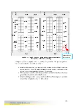
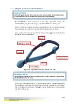
Страница 26: ...4 19 INM12006 MOOMONITOR V3 0 Copyright Dairymaster 2015 Figure 24 Typical MooMonitor Mounting kit assembly...

Страница 27: ...and or become a choke hazard When fitting the MooMonitor to the cow thread the collar through the weight to the midpoint of the collar strap Thread the locking ring into place over the weight Add the...

Страница 28: ...V3 0 Copyright Dairymaster 2015 Figure 27 Typical View of the MooMonitor on the Cow RHS Figure 26 Typical view of the MooMonitor on the Cow LHS MooMonitor Collar Buckle Ensure a tight fit so the coll...

Страница 29: ...e 29 Typical View of the MooMonitor installed on the cow The Weight should be centred on the cow s neck to ensure the MooMonitor stays in position Figure 28 Typical view of MooMonitor installed on a c...

Страница 30: ...4 2 INM12006 MOOMONITOR V3 0 Copyright Dairymaster 2015 Figure 30 MooMonitor Collar Assembly North America...

Страница 31: ...4 3 INM12006 MOOMONITOR V3 0 Copyright Dairymaster 2015 Figure 31 MooMonitor Collar Assembly Europe...

Страница 32: ...4 4 INM12006 MOOMONITOR V3 0 Copyright Dairymaster 2015 Figure 32 MooMonitor Collar Assembly Australia New Zealand...

Страница 33: ...connection to the plant supplied by Dairymaster which is in accordance with the legal and statutory requirements for the region of installation Dairymaster warranties for electrical equipment require...

Страница 34: ...MOOMONITOR V3 0 Copyright Dairymaster 2015 Figure 34 Connections onto the Base Station Power Indicator GSM Connection GPS Connection 12V Power CAT 6 Connection UART to USB Connection Wi Fi Antenna IS...

Страница 35: ...base station through the large gland at the base of the unit and into the adapter inside As Standard Each PCB is preconfigured with the following 1 SD card reader 2 Wi Fi module CAT 6 Module Model De...

Отзывы: