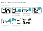
background image

Installation Guide

Daintree

®

 Networked Wireless Adapter (WA100-PM)

15

11

13

14

After the Installation Test is complete the WA100-PM is ready to 

communicate with the Daintree Wireless Area Controller

(WAC) and the Daintree Controls Software (DCS) web-based 

lighting management user interface. Upon commissioning,

the WA100-PM “Join” LED turns on solid and remains on as long 

as the WA100-PM is included in the ZigBee Network.
After joining the network, the low voltage devices connected to 

the WA100-PM do not directly control the lights that are

wired to the same WA100-PM. The control signals from the low 

voltage devices pass through the WA100-PM and are sent

wirelessly to the Daintree Networked. Depending on the zone 

and device configuration in the DCS, wireless signals from

the WAC to the WA100-PM determine the operation of the 

light(s).
For more information about configuring the lighting control 

network, see the instructions and on-line help provided with 

the Daintree Controls Software web application.

The Installation Test procedure fails. 


1.

  Confirm that the WA100-PM is powered.


2.

 Check the connections from the WA100-PM to the driver(s)  


  and low voltage control devices.


3. 

 Check to be sure the WA100-PM DIP switch settings 


  are correct.


4.  

Press and hold the Reset button for 3 seconds to reset 


  the WA100-PM.


5.

 Perform the Installation Test again.

Connected lights do not turn Off during the occupancy sensor 

Installation Test.


1.

   Make sure the sensor is not detecting occupancy.


2. 

Check the occupancy sensor time delay and make sure it is  


  set for minimum. 


When the Daintree Networked is commissioned, time delays are 

set in the Daintree Controls Software system. These DCS “Off delays” 

start counting down after the sensor’s internal time delay expires. 

Therefore, set occupancy sensors for the minimum time delay 

during the WA100-PM installation.

The red Error LED is flashing once every second.

DIP switch configuration is invalid. At least one DIP switch must be 

On to enable an interface.


1.  

Enable the interface(s) that are connected by turning 


  appropriate DIP switch(es) On.


2. 

 Press the blue 

Reset

 button for 

3 seconds

 to reset the unit.

Joining the Zigbee Lighting Control Network

12

Troubleshooting

This equipment has been tested and found to comply with 

the limits for a Class B digital device, pursuant to Part 15 of 

the FCC Rules. These limits are designed to provide reasonable 

protection against harmful interference in a residential 

installation. This equipment generates, uses and radiates radio 

frequency energy and, if not installed and used in accordance 

with the instructions, may cause harmful interference to radio 

communications. However, there is no guarantee that 

interference will not occur in a particular installation. If this 

equipment does cause harmful interference to radio or television 

reception, which can be determined by turning the equipment 

off and on, the user is encourage to try to correct the 

interference by one or more of the following measures:
  •   Reorient or relocate the receiving antenna;
  •   Increase the separation between the equipment

    and receiver;
  •   Connect the equipment into an outlet on a circuit different   

    from that to which the receiver is connected;
  •   Consult the dealer or an experienced radio/TV technician 

    for help.

Product complies with Part 15 of the FCC Rules. Operation is 

subject to the following two conditions: (1) This device may not 

cause harmful interference, and (2) This device must accept any 

interference received, including interference that may cause 

undesired operation. CAN ICES-005 B / NMB-005 B

FCC Warning Message

Industry Canada (IC) Warning Message

Содержание GE Current WA100-PM

Страница 1: ...network and controls lights The WA100 PM is an AC powered device that provides On Off switching as well as 0 10V analog dimming control for LED drivers and ballasts It also provides power for low volt...

Страница 2: ...n Off no dimming provides On Off control using its line voltage Switched Load connection and its low voltage digital output to an external relay Note both outputs are switched at the same time in this...

Страница 3: ...he Black Hot flying lead and the Red Switched Load flying lead are 14AWG The White Neutral flying lead is 18AWG Low voltage 22AWG flying leads provide for connections to supply low voltage power and c...

Страница 4: ...Wireless Adapter WA100 PM 4 Figure 3 Wiring Identification Figure 4 Dimming Light Fixtures 7 Wiring Continued Perform Installation Test Suite 1 DIP Switches Driver Type On Off 0 10V dimming Wired Sens...

Страница 5: ...s Occupancy Sensor configuration This configuration allows the WA100 PM to provide automatic On Off switching based on occupancy Set occupancy sensor for minimum time delay 7 Wiring Continued Perform...

Страница 6: ...or for minimum time delay Figure 8 Dimming Light Fixture s Photosensor configuration This configuration allows the WA100 PM to provide automatic 0 10V dimming control and to switch light fixtures On O...

Страница 7: ...ght Fixture s and Switch configuration This configuration allows the WA100 PM to provide 0 10V dimming control and to switch light fixtures On Off It also provides manual On Off control through a low...

Страница 8: ...ching This configuration allows the WA100 PM to alternate in switching separate drivers providing no load 0 partial load according to the driver loading or full load 100 Always connect the smaller pro...

Страница 9: ...gure 14 208V 2 Pole Phase to Phase wiring This configuration allows the WA100 PM to provide On Off switching of a branch circuit 7 Wiring Continued OFF ON OFF ON Perform Installation Test Suite 1 DIP...

Страница 10: ...gure 15 Switching Contactors This configuration allows the WA100 PM to provide On Off switching control to an external contactor 7 Wiring Continued OFF ON Perform Installation Test Suite 1 DIP Switche...

Страница 11: ...V output from the WA100 PM and the Emergency Light Fixture operates at maximum output from the Emergency power circuit Note If the RRU 2 is not installed the Emergency Fixture will dim to minimum beca...

Страница 12: ...is included with the WA100 PM Affix this label to the outside of the fixture Choose a standard location so that when someone looks for fixtures containing a WA100 PM they will easily find it Using the...

Страница 13: ...e 2 Any Driver Occupancy Sensor 1 Press and immediately release the blue Reset button The red Error LED flashes once then pauses and repeats 2 Check that the connected lights cycle On and Off or cycle...

Страница 14: ...the green Joined LED and the red Error LEDs begin flashing Test Suite 4 Continued 4 Operate the switch es connected to the WA100 PM and observe that the lights turn On Off and Dim as expected 5 Press...

Страница 15: ...own after the sensor s internal time delay expires Therefore set occupancy sensors for the minimum time delay during the WA100 PM installation The red Error LED is flashing once every second DIP switc...

Страница 16: ...lug load circuit Wiring for Combination Plug Load Basic Aux Relay and On Off Light In the wiring diagram below the WA100 PM is used to control both an On Off light and a plug load circuit Plug Load Ap...

Страница 17: ...plug load circuit Plug Load Applications Continued Perform Installation Test Suite 1 DIP Switches Driver On Off 0 10V dimming Plug Load On Off Wired Sensor None On 1 2 3 4 5 6 2 3 On OFF ON 0 10V Dim...

Страница 18: ...t and a plug load circuit Plug Load Applications Continued Perform Installation Test Suite 1 DIP Switches Driver On Off Plug Load On Off Wired Sensor None On 1 2 3 4 5 6 2 4 On OFF ON 0 10V Dimming ou...

Страница 19: ...RECT TYPE DISPOSAL OF USED BATTERIES ACCORDING TO THE INSTRUCTIONS WFA100 PM Input Voltage 120 277VAC 50 60Hz Switched Output 15A driver incandescent 120 277VAC Relay 1hp 120 230VAC switched to Hot Ac...

Отзывы: