


Function of Main Components and Thermistors
ESIE12-06
94
Function and Control
1. Function of Main Components and Thermistors
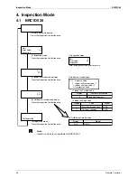
RZQG71L
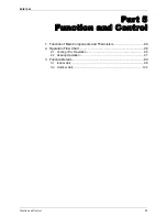
RZQG100-140L
* This thermistor is near the el. compo. box.
*
R4T
R3T
S1PH
R6T
R2T
R1T
R5T
R2T R3T
R1T
Filter
Filter
(C) Four way valve
Indoor heat exchanger
Field piping
φ
9.5
C1220T-O
Field piping
φ
15.9
Accumulator
(A) Compressor
C1220T-O
Indoor unit
Outdoor unit
Stop valve
(with service port 5/16" flare)
Outdoor
heat exchanger
(B)Electronic
expansion valve
Compressor
Accumulator
Pressure
switch
(high)
Service port
(5/16" flare)
Check valve
C: 3D069535
R2T R3T
R1T
* This thermistor is near the el. compo. box.
Indoor heat exchanger
Indoor unit
Field piping
φ
9.5
C1220T-O
Field piping
φ
15.9
C1220T-O
Stop valve
(with service port 5/16" flare)
Filter
Filter
Outdoor
heat exchanger
(B)Electronic
expansion valve
R3T
S1PH
R6T
R2T
(C) Four way valve
Accumulator
Compressor
Accumulator
Pressure
switch
(high)
(A) Compressor
Outdoor unit
*
R4T
R1T
R5T
Service port
(5/16" flare)
C: 3D069536
Содержание RZQG71~140L7V1B
Страница 2: ......
Страница 14: ...ESIE12 06 Outlook Outdoor Units General Information 3 2 Outlook Outdoor Units...
Страница 15: ...Outlook Outdoor Units ESIE12 06 4 General Information...
Страница 16: ...ESIE12 06 Functions 5 Part 2 Functions 1 Functions 5 1 1 Indoor Unit 5 1 2 Outdoor Unit 5...
Страница 18: ...ESIE12 06 Specifications 7 Part 3 Specifications 1 Specifications 8 2 Operation range 75...
Страница 19: ...Specifications ESIE12 06 8 Specifications 1 Specifications RZQG71V FVQ71CVEB RZQG71L7V1B...
Страница 20: ...ESIE12 06 Specifications Specifications 9 FUQ71BWV1B RZQG71L7V1B FUQ71BVV1B RZQG71L7V1B...
Страница 21: ...Specifications ESIE12 06 10 Specifications FHQG71CVEB RZQG71L7V1B FCQHG71FVEB RZQG71L7V1B...
Страница 22: ...ESIE12 06 Specifications Specifications 11 FCQG71FVEB RZQG71L7V1B FBQ71C8VEB RZQG71L7V1B...
Страница 23: ...Specifications ESIE12 06 12 Specifications FAQ71CVEB RZQG71L7V1B...
Страница 24: ...ESIE12 06 Specifications Specifications 13 RZQG71L7V1B...
Страница 25: ...Specifications ESIE12 06 14 Specifications RZQG71Y FVQ71CVEB RZQG71L7Y1B...
Страница 26: ...ESIE12 06 Specifications Specifications 15 FUQ71BWV1B RZQG71L7Y1B FHQG71CVEB RZQG71L7Y1B...
Страница 27: ...Specifications ESIE12 06 16 Specifications FCQHG71FVEB RZQG71L7Y1B FCQG71FVEB RZQG71L7Y1B...
Страница 28: ...ESIE12 06 Specifications Specifications 17 FBQ71C8VEB RZQG71L7Y1B FAQ71CVEB RZQG71L7Y1B...
Страница 29: ...Specifications ESIE12 06 18 Specifications RZQG71L7Y1B...
Страница 30: ...ESIE12 06 Specifications Specifications 19 RZQG100V FVQ100CVEB RZQG100L7V1B FUQ100BWV1B RZQG100L7V1B...
Страница 31: ...Specifications ESIE12 06 20 Specifications FUQ100BVV1B RZQG100L7V1B FHQG100CVEB RZQG100L7V1B...
Страница 32: ...ESIE12 06 Specifications Specifications 21 FCQHG100FVEB RZQG100L7V1B FCQG100FVEB RZQG100L7V1B...
Страница 33: ...Specifications ESIE12 06 22 Specifications FBQ100C8VEB RZQG100L7V1B FAQ100CVEB RZQG100L7V1B...
Страница 34: ...ESIE12 06 Specifications Specifications 23 RZQG100L7V1B...
Страница 35: ...Specifications ESIE12 06 24 Specifications RZQG100Y FVQ100CVEB RZQG100L7Y1B FUQ100BWV1B RZQG100L7Y1B...
Страница 36: ...ESIE12 06 Specifications Specifications 25 FHQG100CVEB RZQG100L7Y1B FCQHG100FVEB RZQG100L7Y1B...
Страница 37: ...Specifications ESIE12 06 26 Specifications FCQG100FVEB RZQG100L7Y1B FBQ100C8VEB RZQG100L7Y1B...
Страница 38: ...ESIE12 06 Specifications Specifications 27 FAQ100CVEB RZQG100L7Y1B...
Страница 39: ...Specifications ESIE12 06 28 Specifications RZQG100L7Y1B...
Страница 40: ...ESIE12 06 Specifications Specifications 29 RZQG125V FVQ125CVEB RZQG125L7V1B FUQ125BWV1B RZQG125L7V1B...
Страница 41: ...Specifications ESIE12 06 30 Specifications FUQ125BVV1B RZQG125L7V1B FHQG125CVEB RZQG125L7V1B...
Страница 42: ...ESIE12 06 Specifications Specifications 31 FDQ125C7VEB RZQG125L7V1B FCQHG125FVEB RZQG125L7V1B...
Страница 43: ...Specifications ESIE12 06 32 Specifications FCQG125FVEB RZQG125L7V1B FBQ125C8VEB RZQG125L7V1B...
Страница 44: ...ESIE12 06 Specifications Specifications 33 RZQG125L7V1B...
Страница 45: ...Specifications ESIE12 06 34 Specifications RZQG125Y FVQ125CVEB RZQG125L7Y1B FUQ125BWV1B RZQG125L7Y1B...
Страница 46: ...ESIE12 06 Specifications Specifications 35 FHQG125CVEB RZQG125L7Y1B FDQ125C7VEB RZQG125L7Y1B...
Страница 47: ...Specifications ESIE12 06 36 Specifications FCQHG125FVEB RZQG125L7Y1B FCQG125FVEB RZQG125L7Y1B...
Страница 48: ...ESIE12 06 Specifications Specifications 37 FBQ125C8VEB RZQG125L7Y1B...
Страница 49: ...Specifications ESIE12 06 38 Specifications RZQG125L7Y1B...
Страница 50: ...ESIE12 06 Specifications Specifications 39 RZQG140V FVQ140CVEB RZQG140L7V1B FHQG140CVEB RZQG140L7V1B...
Страница 51: ...Specifications ESIE12 06 40 Specifications FCQHG140FVEB RZQG140L7V1B FCQG140FVEB RZQG140L7V1B...
Страница 52: ...ESIE12 06 Specifications Specifications 41 FBQ140C8VEB RZQG140L7V1B...
Страница 53: ...Specifications ESIE12 06 42 Specifications RZQG140L7V1B...
Страница 54: ...ESIE12 06 Specifications Specifications 43 RZQG140Y FVQ140CVEB RZQG140L7Y1B FHQG140CVEB RZQG140L7Y1B...
Страница 55: ...Specifications ESIE12 06 44 Specifications FCQHG140FVEB RZQG140L7Y1B FCQG140FVEB RZQG140L7Y1B...
Страница 56: ...ESIE12 06 Specifications Specifications 45 FBQ140C8VEB RZQG140L7Y1B...
Страница 57: ...Specifications ESIE12 06 46 Specifications RZQG140L7Y1B...
Страница 58: ...ESIE12 06 Specifications Specifications 47 RZQSG71V FVQ71CVEB RZQSG71L2V1B FHQG71CVEB RZQSG71L2V1B...
Страница 59: ...Specifications ESIE12 06 48 Specifications FCQHG71FVEB RZQSG71L2V1B FCQG71FVEB RZQSG71L2V1B...
Страница 60: ...ESIE12 06 Specifications Specifications 49 FBQ71C8VEB RZQSG71L2V1B FAQ71CVEB RZQSG71L2V1B...
Страница 61: ...Specifications ESIE12 06 50 Specifications RZQSG71L2V1B...
Страница 62: ...ESIE12 06 Specifications Specifications 51 RZQSG71V FVQ100CVEB RZQSG100L7V1B FHQG100CVEB RZQSG100L7V1B...
Страница 63: ...Specifications ESIE12 06 52 Specifications FCQHG100FVEB RZQSG100L7V1B FCQG100FVEB RZQSG100L7V1B...
Страница 64: ...ESIE12 06 Specifications Specifications 53 FBQ100C8VEB RZQSG100L7V1B FAQ100CVEB RZQSG100L7V1B...
Страница 65: ...Specifications ESIE12 06 54 Specifications RZQSG100L7V1B...
Страница 66: ...ESIE12 06 Specifications Specifications 55 RZQSG100Y FVQ100CVEB RZQSG100L7Y1B FHQG100CVEB RZQSG100L7Y1B...
Страница 67: ...Specifications ESIE12 06 56 Specifications FCQHG100FVEB RZQSG100L7Y1B FCQG100FVEB RZQSG100L7Y1B...
Страница 68: ...ESIE12 06 Specifications Specifications 57 FBQ100C8VEB RZQSG100L7Y1B FAQ100CVEB RZQSG100L7Y1B...
Страница 69: ...Specifications ESIE12 06 58 Specifications RZQSG100L7Y1B...
Страница 70: ...ESIE12 06 Specifications Specifications 59 RZQSG125V FVQ125CVEB RZQSG125L7V1B FHQG125CVEB RZQSG125L7V1B...
Страница 71: ...Specifications ESIE12 06 60 Specifications FDQ125C7VEB RZQSG125L7V1B FCQHG125FVEB RZQSG125L7V1B...
Страница 72: ...ESIE12 06 Specifications Specifications 61 FCQG125FVEB RZQSG125L7V1B FBQ125C8VEB RZQSG125L7V1B...
Страница 73: ...Specifications ESIE12 06 62 Specifications RZQSG125L7V1B...
Страница 74: ...ESIE12 06 Specifications Specifications 63 RZQSG125Y FVQ125CVEB RZQSG125L7Y1B FHQG125CVEB RZQSG125L7Y1B...
Страница 75: ...Specifications ESIE12 06 64 Specifications FDQ125C7VEB RZQSG125L7Y1B FCQHG125FVEB RZQSG125L7Y1B...
Страница 76: ...ESIE12 06 Specifications Specifications 65 FCQG125FVEB RZQSG125L7Y1B FBQ125C8VEB RZQSG125L7Y1B...
Страница 77: ...Specifications ESIE12 06 66 Specifications RZQSG125L7Y1B...
Страница 78: ...ESIE12 06 Specifications Specifications 67 RZQSG140V FVQ140CVEB RZQSG140L7V1B FHQG140CVEB RZQSG140L7V1B...
Страница 79: ...Specifications ESIE12 06 68 Specifications FCQHG140FVEB RZQSG140L7V1B FCQG140FVEB RZQSG140L7V1B...
Страница 80: ...ESIE12 06 Specifications Specifications 69 FBQ140C8VEB RZQSG140L7V1B...
Страница 81: ...Specifications ESIE12 06 70 Specifications RZQSG140L7V1B...
Страница 82: ...ESIE12 06 Specifications Specifications 71 RZQSG140Y FVQ140CVEB RZQSG140L7Y1B FHQG140CVEB RZQSG140L7Y1B...
Страница 83: ...Specifications ESIE12 06 72 Specifications FCQHG140FVEB RZQSG140L7Y1B FCQG140FVEB RZQSG140L7Y1B...
Страница 84: ...ESIE12 06 Specifications Specifications 73 FBQ140C8VEB RZQSG140L7Y1B...
Страница 85: ...Specifications ESIE12 06 74 Specifications RZQSG140L7Y1B...
Страница 86: ...ESIE12 06 Operation range Specifications 75 2 Operation range Smart...
Страница 87: ...Operation range ESIE12 06 76 Specifications EDP...
Страница 88: ...ESIE12 06 Operation range Specifications 77 Classic...
Страница 89: ...Operation range ESIE12 06 78 Specifications...
Страница 131: ...Function Details ESIE12 06 120 Function and Control limit and or Tc Upper limit...
Страница 161: ...Field Setting from Outdoor Unit PCB ESIE12 06 150 Field Setting Outdoor unit...
Страница 162: ...ESIE12 06 Field Setting from Outdoor Unit PCB Field Setting 151 3 2 7 Troubleshooting...
Страница 165: ...Emergency Operation ESIE12 06 154 Field Setting...
Страница 265: ...ESIE12 06 254 Service Diagnosis...
Страница 279: ...Precautions for New Refrigerant R 410A ESIE12 06 268 Appendix...


