background image

Installation and operation manual

58

RXYQQ8~20T7Y1B

VRV IV System Air Conditioner

4P345099-1 – 2013.04

10. Troubleshooting

If one of the following malfunctions occur, take the measures shown
below and contact your dealer.

The system must be repaired by a qualified service person:

If a safety device such as a fuse, a breaker or an earth leakage
breaker frequently actuates or the ON/OFF switch does not
properly work. 
Measure: Turn off the main power switch.

If water leaks from the unit. 
Measure: Stop the operation.

The operation switch does not work well. 
Measure: Turn off the power.

If the user interface display indicates the unit number, the
operation lamp flashes and the malfunction code appears.
Measure: Notify your installer and report the malfunction code.

If the system does not properly operate except for the above
mentioned cases and none of the above mentioned malfunctions is
evident, investigate the system according to the following
procedures.

If the system does not operate at all:

Check if there is no power failure. 
Wait until power is restored. If power failure occurs during
operation, the system automatically restarts immediately
after the power supply is recovered.

Check if no fuse has blown or breaker has worked.
Change the fuse or reset the breaker if necessary.

If the system goes into fan only operation, but as soon as it goes
into heating or cooling operation, the system stops:
Check if air inlet or outlet of outdoor or indoor unit is not blocked
by obstacles. Remove any obstacle and make it well-ventilated.
Check if the user interface display shows 

 (time to clean the

air filter). (Refer to 

"17. Maintenance and service" on page 46

and "Maintenance" in the indoor unit manual.)

The system operates but cooling or heating is insufficient:

Check if air inlet or outlet of outdoor or indoor unit is not
blocked by obstacles.

Remove any obstacle and make it well-ventilated.

Check if the air filter is not clogged (refer to "Maintenance" in
the indoor unit manual).

Check the temperature setting.

Check the fan speed setting on your user interface.

Check for open doors or windows. Shut doors and windows
to prevent wind from coming in.

Check if there are too many occupants in the room during
cooling operation. Check if the heat source of the room is
excessive.

Check if direct sunlight enters the room. Use curtains or
blinds.

Check if the air flow angle is proper.

If after checking all above items, it is impossible to fix the problem
yourself, contact your installer and state the symptoms, the complete
model name of the air conditioner (with manufacturing number if
possible) and the installation date (possibly listed on the warranty
card).

11. After-sales service and warranty

11.1. Warranty period

This product includes a warranty card that was filled in by the
dealer at the time of installation. The completed card has to be
checked by the customer and stored carefully.

If repairs to the air conditioner are necessary within the warranty
period, contact your dealer and keep the warranty card at hand.

11.2. After-sales service

11.2.1. Recommendations for maintenance and inspection

Since dust collects when using the unit for several years,
performance of the unit will deteriorate to some extent. As taking
apart and cleaning interiors of units requires technical expertise and
in order to ensure the best possible maintenance of your units, we
recommend to enter into a maintenance and inspection contract on
top of normal maintenance activities. Our network of dealers has
access to a permanent stock of essential components in order to
keep your air conditioner in operation as long as possible. Contact
your dealer for more information.

When asking your dealer for an intervention, always state:

The complete model name of the air conditioner.

The manufacturing number (stated on the nameplate of the unit).

The installation date.

The symptoms or malfunction, and details of the defect.

11.2.2. Recommended inspection and maintenance cycles

Be aware that the mentioned maintenance and replacement cycles
do not relate to the warranty period of the components.

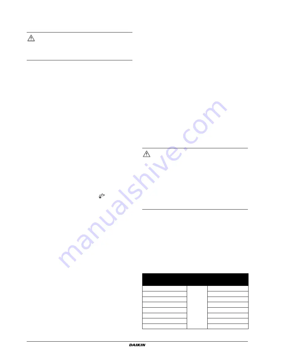
Table 1: "Inspection Cycle" and "Maintenance Cycle" list

Table 1 assumes the following conditions of use:

Normal use without frequent starting and stopping of the unit.
Depending on the model, we recommend not starting and
stopping the machine more than 6 times/hour.

Operation of the unit is assumed to be 10 hours/day and 2,500
hours/year.

Table 1

WARNING

Stop operation and shut off the power if anything
unusual occurs (burning smells etc.).

Leaving the unit running under such circumstances may
cause breakage, electric shock or fire. Contact your dealer.

WARNING

Do not modify, disassemble, remove, reinstall or
repair the unit yourself as incorrect dismantling or
installation may cause an electric shock or fire.
Contact your dealer.

In case of accidental refrigerant leaks, make sure
there are no naked flames. The refrigerant itself is
entirely safe, non-toxic and non-combustible, but it will
generate toxic gas when it accidentally leaks into a
room where combustible air from fan heaters, gas
cookers, etc. is present. Always have qualified service
personnel confirm that the point of leakage has been
repaired or corrected before resuming operation.

Component

Inspection 

cycle

Maintenance cycle 

(replacements and/or 

repairs)

Electric motor

1 year

20,000 hours

PCB

25,000 hours

Heat exchanger 

5 years

Sensor (thermistor, etc.)

5 years

User interface and switches

25,000 hours

Drain pan

8 years

Expansion valve

20,000 hours

Solenoid valve

20,000 hours

Содержание RXYQQ8T7Y1B

Страница 1: ...INSTALLATION AND OPERATION MANUAL RXYQQ8T7Y1B RXYQQ10T7Y1B RXYQQ12T7Y1B RXYQQ14T7Y1B RXYQQ16T7Y1B RXYQQ18T7Y1B RXYQQ20T7Y1B System Air Conditioner...

Страница 2: ...H HPS R8T 10 12HP 3 6 15 4 5 18 17 7 8 14 1 16 11 12 10 1 2 10 10 13 12 6 11 9 7 14 18 17 8 18 3 5 4 4 5 M sv sv INV INV sv M1C M2C M1F M M2F S1NPH S1NPL S1PH S2PH HPS R6T R5T R7T R1T R4T R8T 10 12HP...

Страница 3: ...A og gjennom positiv bed mmelse av B if lge Sertifikat C som det fremkommer i den Tekniske Konstruksjonsfilen D og gjennom positiv bed mmelse av E Anvendt modul F G Risikokategori H Se ogs neste side...

Страница 4: ...PS vastav k llastunud temperatuur M C Jahutusaine N Surve turvaseadme seadistus P bar Tootmisnumber ja tootmisaasta vaadake mudeli andmeplaati 21 PS K bar TS TSmin L C TSmax PS M C N P bar 22 Maksimal...

Страница 5: ...29 13 3 Connecting the PC configurator to the outdoor unit 30 14 Charging refrigerant 30 14 1 Precautions 30 14 2 Important information regarding the refrigerant used 31 14 3 Calculating the addition...

Страница 6: ...ning service In Europe EN 378 provides the necessary guidance for this logbook 3 Introduction 3 1 General information This installation manual concerns the VRV IV full inverter driven heat pump system...

Страница 7: ...hese here below are prohibited To install the outdoor unit the following optional parts are also required 1 Refrigerant branching kit For the selection of the optimal branching kit please refer to 9 4...

Страница 8: ...1 in the figure below for reference to where following accessories are supplied with the unit INFORMATION Refer to the technical engineering data for the latest option names HP class of outdoor unit 5...

Страница 9: ...onnection 9 52 9 52 9 52 12 7 Bottom connection 9 52 9 52 9 52 12 7 Accessory pipes mm 14 HP 16 HP 18 HP a b a b a b Gas pipe Front connection 25 4 28 6 25 4 28 6 25 4 28 6 Bottom connection 25 4 28 6...

Страница 10: ...main component list may not be existing in the unit Main components see figure 1 figure 2 figure 3 figure 4 1 Compressor M1C 2 Compressor M2C 3 Heat exchanger 4 Fan 5 Fan motor M1F M2F 6 Accumulator 7...

Страница 11: ...ty limits in the event of a refrigerant leak refer to 18 Caution for refrigerant leaks on page 47 1 Personal computer or radio 2 Fuse 3 Earth leakage protector 4 User interface 5 Indoor unit 6 Outdoor...

Страница 12: ...ion may result in the unit turning over 6 2 Weather related precautions Select a place where the rain can be avoided as much as possible Be sure that the air inlet of the unit is not positioned toward...

Страница 13: ...any indicated service space dimensions 4 15x22 5 515 76 765 76 272 328 373 930 97 107 131 179 259 276 122 766 729 137 1685 mm RXYQQ8 12 4 15x22 5 97 272 328 373 1240 107 131 179 259 276 122 1685 76 13...

Страница 14: ...Unpacking Relief the unit from its packing material Take care not to damage the unit when removing the shrink foil with a cutter 1 Remove the 4 bolts fixing the unit to its pallet 2 Make sure that all...

Страница 15: ...en care of the area around the unit might be very slippery When installed in a corrosive environment use a nut with plastic washer 1 to protect the nut tightening part from rust NOTICE If the unit is...

Страница 16: ...e of the main pipes 1 Outdoor unit 2 Main pipes 3 Increase 4 First refrigerant branch kit 5 Indoor unit The pipe thickness of the refrigerant piping shall comply with the applicable legislation The mi...

Страница 17: ...h the number of outdoor units 9 5 System piping length limitations 9 5 1 Piping length restrictions Make sure to perform the piping installation within the range of the maximum allowable pipe length a...

Страница 18: ...pe size of the main pipe then the pipe size of the main pipe has to be increased as well Branch with refnet joint Branch with refnet joint and refnet header Branch with refnet header Single outdoor Ex...

Страница 19: ...g follow the instructions in the installation manual that comes with the kit Only proceed with piping work after considering the limitations on installing listed here and in the chapter 10 2 Connectin...

Страница 20: ...ture and contamination from mixing into the system Block all gaps in the holes for passing out piping and wiring using sealing material field supply the capacity of the unit will drop and small animal...

Страница 21: ...stop valves cut off the lower part of the smaller pinched piping with an appropriate tool e g pipe cutter a pair of nippers Let the remaining oil drip out in case the recovery was not complete Wait un...

Страница 22: ...oint vertically see view B 2 Make sure that the total length of the piping connected to the joint is absolute straight for more than 500 mm Only if a straight field piping of more than 120 mm is conne...

Страница 23: ...Schrader type valve After handling the service port make sure to tighten the service port cover securely For the tightening torque refer to the table below Check for refrigerant leaks after tightenin...

Страница 24: ...eak test and vacuum drying on page 19 10 4 4 Setup 1 Pressure reducing valve 2 Nitrogen 3 Measuring instrument 4 Refrigerant R410A tank siphon system 5 Vacuum pump 6 Charge hose 7 Refrigerant charge p...

Страница 25: ...ing work 12 1 Precautions on electrical wiring work For the existing power supply and transmission wiring check that the specifications match the requirements as described in this chapter and that oth...

Страница 26: ...sure to install an earth leakage protector in accordance with the applicable legislation Failure to do so may cause electric shock or fire Be sure to use a dedicated power circuit never use a power s...

Страница 27: ...rn Y3S Solenoid valve oil 1 Y4S Solenoid valve oil 2 Z1C Z7C Noise filter ferrite core Z1F Noise filter with surge absorber L1 L2 L3 Live N Neutral Field wiring Terminal strip Connector Terminal Prote...

Страница 28: ...500 m Maximum number of branches 16 Maximum number of independent interconnectable systems 10 Up to 16 branches are possible for unit to unit cabling No branching is allowed after branching see figur...

Страница 29: ...Transmission wiring 2 Fix wiring with tie wrap 3 Possible power supply wire entrance hole 6 4 Possible transmission wire entrance hole 6 5 Possible transmission wire entrance hole 6 Fix wiring to pipe...

Страница 30: ...e 7 5 Alternative power supply routing 12 6 3 Precautions when knocking out knockout holes To punch a knockout hole hit on it with a hammer After knocking out the holes we recommend removing any burrs...

Страница 31: ...the indoor units is connected 12 7 2 Connection of wiring to terminals Transmission wiring in outdoor unit 1 Fix to the indicated plastic brackets using field supplied clamping material 2 Wiring betw...

Страница 32: ...ical component box service cover Operate the switches and push buttons with an insulated stick such as a closed ball point pen to avoid touching of live parts Make sure to re attach the inspection cov...

Страница 33: ...ordingly The communication wiring should be checked at first Accessing modes BS1 is used to change the mode you want to access Access mode 1 Push BS1 one time Segment indication changes to Access mode...

Страница 34: ...by pushing BS3 To leave the monitoring function push BS1 2 times you will return to the default situation when shipped from factory 13 2 2 Operating the DIP switches By operating the DIP switches it...

Страница 35: ...ping please take into account following table concerning the weight factor to be allocated It should be substituted in the formula for R When selecting indoor unit following table with connection rati...

Страница 36: ...14 3 Calculating the additional refrigerant charge on page 31 Refrigerant overcharge happened Recover refrigerant to reach R Q Go to step 4a Step 2 3 Open valve C to field piping via liquid stop valv...

Страница 37: ...tically PE charging nearly finished P9 charging finished OR P kg was added during autocharge R Q P Close valve A Push BS1 to leave program Charging is finished Fill in the amount on the additional ref...

Страница 38: ...b If the total amount of refrigerant could not be charged by pre charging then close valve C and go to step 5 Follow step 6 depending on the chosen charging method 5 After pre charging perform the ref...

Страница 39: ...ating close valve A immediately and check whether the segment indication user interface of indoor unit shows P9 This indicates the automatic charging in cooling program was finished successfully If du...

Страница 40: ...nel The voltage must correspond to the voltage on the identification label of the unit 4 Earth wiring Be sure that the earth wires have been connected properly and that the earth terminals are tighten...

Страница 41: ...mes The second method is to enable low noise operation based on an external input For this operation an optional accessory is required 1 2 shows the status of power consumption limitation operation 1...

Страница 42: ...limitation via external control adaptor DTA104A61 62 If the system needs to be running under low noise operation or under power consumption limitation conditions when an external signal is sent to th...

Страница 43: ...a the external control adaptor DTA104A61 62 If the system needs to be running under power consumption limitation conditions when an external signal is sent to the unit this setting defines the level p...

Страница 44: ...e customer The selection method of indoor units is important and has to be considered as the available capacity is not the same as under basic operation For details concerning to Hi sensible applicati...

Страница 45: ...hieve the required room temperature very fast The overshoot is not allowed from the start up moment The start up occurs under the condition which is defined by the operation mode above In case of cool...

Страница 46: ...temperature evolution A Indoor unit set temperature B Operation start C Operating time D Mild E Quick F Powerful Example Automatic mode during heating A Virtual load curve default automatic mode peak...

Страница 47: ...witches on the logic board on page 29 Push BS2 for 5 seconds or more The unit will start test operation The test operation is automatically carried out the outdoor unit display will indicate t01 and t...

Страница 48: ...d stop valve 18 Refrigerant overcharge Stop valve closed Check refrigerant amount recharge unit Open stop valves E4 01 02 03 Low pressure malfunction Stop valve closed Refrigerant shortage Indoor unit...

Страница 49: ...26 29 INV2 power phase loss Check if power supply is within range U3 03 Malfunction code System test run not yet executed system operation not possible Execute system test run U4 01 Faulty wiring to Q...

Страница 50: ...GER Electrical shock See 2 General safety precautions on page 2 CAUTION When performing service to inverter equipment 1 Do not open the electrical component box cover for 10 minutes after the power su...

Страница 51: ...l applicable regulations and standards for the maximum allowable concentration level is required According to the appropriate European Standard the maximum allowed concentration level of refrigerant t...

Страница 52: ...ty devices High pressure switch Fan driver overload protector Inverter overload protector PC board fuse a Nominal cooling capacities are based on indoor temperature 27 C DB and 19 C WB outdoor tempera...

Страница 53: ...fault circuit interrupter earth leakage circuit breaker A 20 25 32 Total overcurrent amps TOCA e e TOCA means the total value of each OC set A 17 3 24 6 35 4 Full load amps FLA f f FLA nominal running...

Страница 54: ...cified for a certain product or application which explains if relevant how to install configure operate and or maintain the product or application Dealer Sales distributor for products as per the subj...

Страница 55: ...lectric shock and fire Do not insert fingers rods or other objects into the air inlet or outlet When the fan is rotating at high speed it will cause injury Never let the indoor unit or the user interf...

Страница 56: ...lems may happen For checking and adjusting the internal parts contact your dealer Do not touch the heat exchanger fins These fins are sharp and could result in cutting injuries NOTICE Never put any ob...

Страница 57: ...peration operation will restart automatically after the power turns back on again 6 1 Cooling heating fan only and automatic operation Changeover cannot be made with a user interface whose display sho...

Страница 58: ...starts operating 3 Press the air flow direction adjust button only for Double flow Multi flow Corner Ceiling suspended and Wall mounted Refer to 6 3 Adjusting the air flow direction on page 54 for det...

Страница 59: ...a room during cooling operation by using curtains or blinds Ventilate often Extended use requires special attention to ventilation Keep doors and windows closed If the doors and windows remain open a...

Страница 60: ...ars 8 2 Maintenance before a long stop period e g at the end of the season Let the indoor units run in fan only operation for about half a day in order to dry the interior of the units Refer to 6 1 Co...

Страница 61: ...eard immediately after the power supply is turned on The electronic expansion valve inside an indoor unit starts working and makes the noise Its volume will reduce in about one minute A continuous low...

Страница 62: ...After sales service and warranty 11 1 Warranty period This product includes a warranty card that was filled in by the dealer at the time of installation The completed card has to be checked by the cus...

Страница 63: ...mponents Refer to your maintenance and inspection contract for more details Table 2 Replacement Cycle list indicates recommended intervals of replacement cycles However in order to keep the unit opera...

Страница 64: ...rmistor malfunction P8 Autocharge operation related P9 Autocharge operation related PE Autocharge operation related PJ Capacity setting malfunction outdoor U0 Abnormal low pressure drop faulty expansi...

Страница 65: ......

Страница 66: ......

Страница 67: ......

Страница 68: ...4P345099 1 2013 04 Copyright 2013 Daikin 4P345099 1 0000000S...

Отзывы: