


Installation manual
11
RX(Y)Q5-10-1 RXQ RXYQ
RXYHQ1 RX(Y)Q14~18P7W1BA
VRVIII System air conditioner
4PW48461-1
7.
L
EAK
TEST
AND
VACUUM
DRYING
The units were checked for leaks by the manufacturer.
After connecting the field piping, perform the following inspections.
1
Preparations
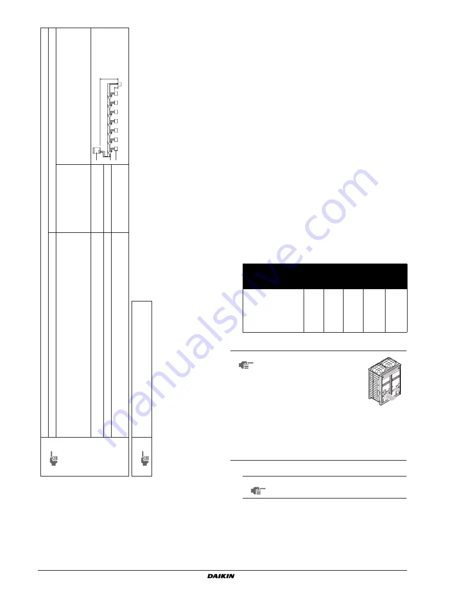
Referring to
figure 27
, connect a nitrogen tank, a cooling tank,
and a vacuum pump to the outdoor unit and perform the
airtightness test and the vacuum drying. The stop valve and
valves A and B in
figure 27
should be open and closed as shown
in the table below when performing the airtightness test and
vacuum drying.
2
Airtightness test and vacuum drying
■
Airtightness test:
Pressurize the liquid and gas pipes to 4.0 MPa (40 bar) (do not
pressurize more than 4.0 MPa (40 bar)). If the pressure does not
drop within 24 hours, the system passes the test. If the pressure
drops, check where the nitrogen leaks from.
Note 1
Allo
w
a
b
le length after the first refr
iger
ant br
anch kit to indoor units is 40 m or less
, ho
w
e
v
er it can be e
xtended up to 90 m i
f all the f
ollo
wing conditions are fulfilled.
Required conditions
Example dra
wings
It is necessar
y to increase the pipe siz
e of the liquid and the gas pipe if the pipe length betw
een the first
and the final br
anch kit is o
v
er 40 m (reducers m
ust be procured on site).
If the increased pipe siz
e is larger than the pipe siz
e of the main pipe
, then the pipe siz
e of the main pipe
needs to be increased as w
ell.
indoor unit
8
:
b+c+d+e+f+g+p
≤
90 m
increase the pipe siz
e
of b
, c
, d, e
, f
, g
Increase the pipe siz
e as f
ollo
ws
* If a
v
ailab
le on the site
. Otherwise it can not be increased.
F
or calculation of total e
xtension length, the actual length of abo
v
e
pipes m
ust be doub
led.
(e
xcept main
pipe and the pipes that not increase the pipe siz
e)
a+b*2+c*2+d*2+e*2+f*2+g*2
+h+i+j+k+l+m+n+p
≤
1000 m
Indoor unit to the nearest br
anch kit
≤
40 m
h, i, j.......
p
≤
40 m
The diff
erence betw
een the distance of the outdoor unit to the f
a
rthest indoor unit and the distance of the
outdoor unit to the nearest indoor unit
≤
40 m
The f
a
rthest indoor unit
8
The nearest indoor unit
1
(a+b+c+d+e+f+g+p)–(a+h)
≤
40 m
Note 2
If the pipe siz
e abo
v
e
the refnet header is Ø34.9 or more
,
KHRQ22M75H is required.
Ø9.5
➞
Ø12.7
Ø15.9
➞
Ø19.1
Ø22.2
➞
Ø25.4*
Ø12.7
➞
Ø15.9
Ø19.1
➞
Ø22.2
Ø28.6
➞
Ø31.8*
Ø34.9
➞
Ø38.1*
ab
c
d
e
f
g
H1
p
AB
C
D
E
F
G
12
3
4
5
6
7
8
H2
hi
j
k
l
m
n
1
2
3
1
Outdoor unit
2
Refnet joints
(a~g)
3
Indoor units (1~8)
1
Pressure reducing valve
2
Nitrogen
3
Measuring instrument
4
Tank (siphon system)
5
Vacuum pump
6
Charge hose
7
Service port for adding refrigerant
8
Liquid line stop valve
9
Gas line stop valve
10
Outdoor unit
11
To indoor unit
12
Stop valve service port
13
Dotted lines represent on site piping
14
Valve B
15
Valve C
16
Valve A
State
of the valves A and B
and the stop valve
Valve
A
Valve
B
Valve
C
Liquid
side
stop
valve
Gas
side
stop
valve
Performing the
airtightness test and
vacuum drying
(Valve A must always be
shut. Otherwise the
refrigerant in the unit will
pour out.)
Close
Open
Open
Close
Close
NOTE
Make sure to perform airtightness test
and vacuum drying using the service
ports of the stop valves of the liquid
side and of the gas side. (For the
service port location, refer to the
"Caution" label attached on the front
panel of the outdoor unit.)
■
See
"11.3. Stop valve operation
procedure" on page 19
for details on handling the
stop valve.
■
To prevent entry of any contamination and to
prevent insufficient pressure resistance, always
use the special tools dedicated for working with
R410A refrigerant.
NOTE
Make sure to use nitrogen gas.
Содержание RXQ5P7W1B
Страница 36: ...NOTES NOTES...
Страница 38: ...4PW48461 1 Copyright Daikin...


