SiUS371901EB
Troubleshooting by Error Code
Part 6 Service Diagnosis
286
L1 - 01
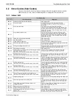
IPM error: Compressor M1C (Master)
Refer to the
L1
flowchart and make a diagnosis of the
relevant unit based on the Error code shown to the left.
L1 - 02
Defective current sensor 1: Compressor M1C (Master)
L1 - 03
Defective current sensor 2: Compressor M1C (Master)
L1 - 04
IGBT error: Compressor M1C (Master)
L1 - 05
Jumper settings error (Master)
L1 - 07
IPM error: Compressor M1C (Slave 1)
L1 - 08
Defective current sensor 1: Compressor M1C (Slave 1)
L1 - 09
Defective current sensor 2: Compressor M1C (Slave 1)
L1 - 10
IGBT error: Compressor M1C (Slave 1)
L1 - 11
IPM error: Compressor M1C (Slave 2)
L1 - 12
Defective current sensor 1: Compressor M1C (Slave 2)
L1 - 13
Defective current sensor 2: Compressor M1C (Slave 2)
L1 - 14
IGBT error: Compressor M1C (Slave 2)
L1 - 15
Jumper settings error (Slave 1)
L1 - 16
Jumper settings error (Slave 2)
L1 - 21
DIP switch settings error (Master)
L1 - 26
DIP switch settings error (Slave 1)
L1 - 36
Defective inverter PCB EEPROM: Compressor M1C
(Master)
L1 - 38
Defective inverter PCB EEPROM: Compressor M1C (Slave
1)
L1 - 40
Defective inverter PCB EEPROM: Compressor M1C
(Slave 2)
L1 - 46
DIP switch settings error (Slave 2)
L1 - 47
15 V power supply error: Compressor M1C (Master)
L1 - 49
15 V power supply error: Compressor M1C (Slave 1)
L1 - 51
15 V power supply error: Compressor M1C (Slave 2)
L2 - 01
Momentary power failure during test operation (Master)
Refer to the
L2
flowchart and make a diagnosis of the
relevant unit based on the Error code shown to the left.
L2 - 02
Momentary power failure during test operation (Slave 1)
L2 - 03
Momentary power failure during test operation (Slave 2)
L2 - 04
Switch ON the power supply (Master)
L2 - 05
Switch ON the power supply (Slave 1)
L2 - 06
Switch ON the power supply (Slave 2)
L3 - 01
Reactor temperature rise: Inverter PCB (Master)
Refer to the
L3
flowchart and make a diagnosis of the
relevant unit based on the Error code shown to the left.
L3 - 03
Reactor temperature rise: Inverter PCB (Slave 1)
L3 - 05
Reactor temperature rise: Inverter PCB (Slave 2)
L4 - 01
Radiation fin temperature rise: Inverter PCB (Master)
Refer to the
L4
flowchart and make a diagnosis of the
relevant unit based on the Error code shown to the left.
L4 - 02
Radiation fin temperature rise: Inverter PCB (Slave 1)
L4 - 03
Radiation fin temperature rise: Inverter PCB (Slave 2)
L4 - 06
Radiation fin temperature rise: Fan M1F (Master)
L4 - 07
Radiation fin temperature rise: Fan M2F (Master)
L4 - 12
Inverter radiation fin temperature rise abnormality (Master)
L4 - 13
Inverter radiation fin temperature rise abnormality (Slave 1)
L4 - 14
Inverter radiation fin temperature rise abnormality (Slave 2)
L4 - 18
Radiation fin temperature rise: Fan M1F (Slave 1)
L4 - 19
Radiation fin temperature rise: Fan M2F (Slave 1)
L4 - 20
Radiation fin temperature rise: Fan M1F (Slave 2)
L4 - 21
Radiation fin temperature rise: Fan M2F (Slave 2)
L5 - 03
Compressor M1C momentary overcurrent (Master)
Refer to the
L5
flowchart and make a diagnosis of the
relevant unit based on the Error code shown to the left.
L5 - 05
Compressor M1C momentary overcurrent (Slave 1)
L5 - 07
Compressor M1C momentary overcurrent (Slave 2)
Error code
Troubleshooting
Error Description
Diagnosis
Содержание REYQ72-432XAYCU
Страница 1: ...Service Manual Heat Recovery 60 Hz REYQ72 456XATJU A REYQ72 456XAYDU A REYQ72 432XAYCU A SiUS371901EB ...
Страница 92: ...Refrigerant Circuit Piping Diagrams SiUS371901EB 85 Part 2 Refrigerant Circuit BSF6Q54TVJ 3D125655 ...
Страница 93: ...SiUS371901EB Refrigerant Circuit Piping Diagrams Part 2 Refrigerant Circuit 86 BSF8Q54TVJ 3D125656 ...
Страница 455: ...SiUS371901EB Wiring Diagrams Part 7 Appendix 448 REYQ144 168XATJU REYQ144 168XATJA 2D119206B ...
Страница 456: ...Wiring Diagrams SiUS371901EB 449 Part 7 Appendix REYQ72 96 120XAYDU REYQ72 96 120XAYDA 2D119207C ...
Страница 457: ...SiUS371901EB Wiring Diagrams Part 7 Appendix 450 REYQ144 168XAYDU REYQ144 168XAYDA 2D119208C ...
Страница 458: ...Wiring Diagrams SiUS371901EB 451 Part 7 Appendix REYQ72 96 120 144 168XAYCU REYQ72 96 120 144 168XAYCA 2D119209B ...
Страница 459: ...SiUS371901EB Wiring Diagrams Part 7 Appendix 452 1 2 Indoor Unit FXFQ07 09 12 15 18 24 30 36 48TVJU 3D086460B ...
Страница 460: ...Wiring Diagrams SiUS371901EB 453 Part 7 Appendix BYCQ125BGW1 Self Cleaning Decoration Panel for FXFQ TVJU 3D076375A ...
Страница 461: ...SiUS371901EB Wiring Diagrams Part 7 Appendix 454 FXZQ05 07 09 12 15 18TAVJU 3D110443A ...
Страница 463: ...SiUS371901EB Wiring Diagrams Part 7 Appendix 456 FXEQ07 09 12 15 18 24PVJU 3D098557A ...
Страница 464: ...Wiring Diagrams SiUS371901EB 457 Part 7 Appendix FXDQ07 09 12 18 24MVJU C 3D050501C ...
Страница 465: ...SiUS371901EB Wiring Diagrams Part 7 Appendix 458 FXSQ05 07 09 12 15 18 24 30 36 48 54TAVJU C 3D110467C ...
Страница 466: ...Wiring Diagrams SiUS371901EB 459 Part 7 Appendix FXMQ07 09 12 15 18 24 30 36 48 54PBVJU 3D093209B ...
Страница 468: ...Wiring Diagrams SiUS371901EB 461 Part 7 Appendix FXHQ12 24 36MVJU 3D048116C ...
Страница 469: ...SiUS371901EB Wiring Diagrams Part 7 Appendix 462 FXAQ07 09 12 18 24PVJU 3D075354F ...
Страница 475: ...SiUS371901EB Wiring Diagrams Part 7 Appendix 468 VAM1200GVJU 3D073270D ...
Страница 477: ...SiUS371901EB Wiring Diagrams Part 7 Appendix 470 1 4 2 Multi Branch Selector Unit Standard Series BS4Q54TVJ 3D089123B ...
Страница 478: ...Wiring Diagrams SiUS371901EB 471 Part 7 Appendix BS6 8Q54TVJ 2D089122B ...
Страница 479: ...SiUS371901EB Wiring Diagrams Part 7 Appendix 472 BS10 12Q54TVJ 2D089121B ...
Страница 480: ...Wiring Diagrams SiUS371901EB 473 Part 7 Appendix 1 4 3 Multi Branch Selector Unit Flex Series BSF4Q54TVJ 3D123904A ...
Страница 481: ...SiUS371901EB Wiring Diagrams Part 7 Appendix 474 BSF6 8Q54TVJ 2D123905A ...

