SiUS371901EB
Test Operation
Part 5 Field Settings and Test Operation
264
Caution
Note(s)
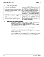
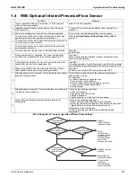
4.3 Gas Furnace Test Operation
Always use the remote controller to stop the test operation.
The test should be performed with the following procedure.
1. All install process, including heat pump system, has been done.
2. Test operation of heat pump system has been successfully completed.
3. Turn off remote controller connected to CXTQ-TA.
4. Change the setting according to the following table.
5. Turn on remote controller connected to CXTQ-TA.
6. The compressor will be forcibly stopped if the compressor is running at this time. After that, the
gas furnace will run in tens of seconds. (Tens of minutes might well be needed to stop
compressor if the outdoor unit is particular operation.)
7. The gas furnace will operate with selected heat stage.
8. This test operation will stop automatically after 30 minutes or when the remote controller is
turned off.
: Factory setting
Heat pump operation is not allowed during this test operation.
When the heat pump is in service mode (test mode, pump down mode, refrigerant charge
mode, etc.), this gas furnace test will not start.
This setting will be returned to factory setting automatically after finishing test operation.
Mode No.
First Code No.
Second Code No.
Gas furnace test mode
14 (24)
11
01
OFF
02
Low heat
03
High heat
Содержание REYQ72-432XAYCU
Страница 1: ...Service Manual Heat Recovery 60 Hz REYQ72 456XATJU A REYQ72 456XAYDU A REYQ72 432XAYCU A SiUS371901EB ...
Страница 92: ...Refrigerant Circuit Piping Diagrams SiUS371901EB 85 Part 2 Refrigerant Circuit BSF6Q54TVJ 3D125655 ...
Страница 93: ...SiUS371901EB Refrigerant Circuit Piping Diagrams Part 2 Refrigerant Circuit 86 BSF8Q54TVJ 3D125656 ...
Страница 455: ...SiUS371901EB Wiring Diagrams Part 7 Appendix 448 REYQ144 168XATJU REYQ144 168XATJA 2D119206B ...
Страница 456: ...Wiring Diagrams SiUS371901EB 449 Part 7 Appendix REYQ72 96 120XAYDU REYQ72 96 120XAYDA 2D119207C ...
Страница 457: ...SiUS371901EB Wiring Diagrams Part 7 Appendix 450 REYQ144 168XAYDU REYQ144 168XAYDA 2D119208C ...
Страница 458: ...Wiring Diagrams SiUS371901EB 451 Part 7 Appendix REYQ72 96 120 144 168XAYCU REYQ72 96 120 144 168XAYCA 2D119209B ...
Страница 459: ...SiUS371901EB Wiring Diagrams Part 7 Appendix 452 1 2 Indoor Unit FXFQ07 09 12 15 18 24 30 36 48TVJU 3D086460B ...
Страница 460: ...Wiring Diagrams SiUS371901EB 453 Part 7 Appendix BYCQ125BGW1 Self Cleaning Decoration Panel for FXFQ TVJU 3D076375A ...
Страница 461: ...SiUS371901EB Wiring Diagrams Part 7 Appendix 454 FXZQ05 07 09 12 15 18TAVJU 3D110443A ...
Страница 463: ...SiUS371901EB Wiring Diagrams Part 7 Appendix 456 FXEQ07 09 12 15 18 24PVJU 3D098557A ...
Страница 464: ...Wiring Diagrams SiUS371901EB 457 Part 7 Appendix FXDQ07 09 12 18 24MVJU C 3D050501C ...
Страница 465: ...SiUS371901EB Wiring Diagrams Part 7 Appendix 458 FXSQ05 07 09 12 15 18 24 30 36 48 54TAVJU C 3D110467C ...
Страница 466: ...Wiring Diagrams SiUS371901EB 459 Part 7 Appendix FXMQ07 09 12 15 18 24 30 36 48 54PBVJU 3D093209B ...
Страница 468: ...Wiring Diagrams SiUS371901EB 461 Part 7 Appendix FXHQ12 24 36MVJU 3D048116C ...
Страница 469: ...SiUS371901EB Wiring Diagrams Part 7 Appendix 462 FXAQ07 09 12 18 24PVJU 3D075354F ...
Страница 475: ...SiUS371901EB Wiring Diagrams Part 7 Appendix 468 VAM1200GVJU 3D073270D ...
Страница 477: ...SiUS371901EB Wiring Diagrams Part 7 Appendix 470 1 4 2 Multi Branch Selector Unit Standard Series BS4Q54TVJ 3D089123B ...
Страница 478: ...Wiring Diagrams SiUS371901EB 471 Part 7 Appendix BS6 8Q54TVJ 2D089122B ...
Страница 479: ...SiUS371901EB Wiring Diagrams Part 7 Appendix 472 BS10 12Q54TVJ 2D089121B ...
Страница 480: ...Wiring Diagrams SiUS371901EB 473 Part 7 Appendix 1 4 3 Multi Branch Selector Unit Flex Series BSF4Q54TVJ 3D123904A ...
Страница 481: ...SiUS371901EB Wiring Diagrams Part 7 Appendix 474 BSF6 8Q54TVJ 2D123905A ...


