


EWWQ090G ÷ EWWQ720L - R410A - Water-cooled scroll chillers
EWLQ090G ÷ EWLQ720L - R410A - Condenser less
EWHQ100G ÷ EWHQ400G - R410A - Heat pump scroll chillers
EWAQ-
- R410A - Air-cooled scroll chillers
EWAQ-
- R410A - Air-cooled scroll chillers
EWYQ-
- R410A - Air-cooled scroll heat pumps
Air and Water cooled scroll chillers & heat pump
Operation
Manual
EWWQ - EWLQ - EWHQ
EWAQ - EWYQ
Air or Water cooled scroll chiller &
heat pump
D-EOMHW00107-15EN
Operation Manual
57
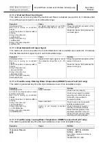
If the Condensing Pressure limit is not reached within the Defrost Timeout limit, the defrost is
finished and the circuit changed over back to heat mode.
If during the defrost the circuit cannot reach the final Condensing Pressure limit before the
timer expires consider to increase this time limit. In case of doubts contact your local
Daikin Service reference.
There are other protections that may stop the defrost before it reaches the Condensing Pressure
limit or the timer expires. In particular if the discharge temperature rises above a safety limit value
the defrost is finished and the circuit change over back to heat mode.
During the whole period of operation in cool mode the fans will never be started to let the
Condensing Pressure reach the limit.
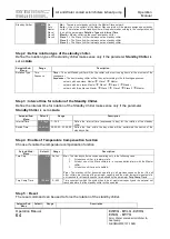
The Defrost will be performed in a sequence of 7 steps:
Nr Phase Description
1
W
Wait for the defrost interstage timer to expire
2
Pr1
Preparation to 4 Way Valve change-over to Cool Mode
3
4W1
4 Way Valve change-over to Cool Mode execution
4
Df
Defrost
5
Pr2
Preparation to 4 Way Valve change-over to Heat Mode
6
4W2
4 Way Valve change-over to Heat Mode execution
7
WuH
Heating Warm-Up (back to normal operation)
5.9 Four Way Valve (H/P gas side reversal only)
The four way valve is managed by each circuit to follow the active unit mode. To guarantee a
proper handling of this device the four way valve can only be commanded with a minimum delta
pressure. This statement implies that the four way valve command can be given only when a
compressor is running.
5.10 Master/Slave
In this section will be described the Master Slave (MS) control logic and all scenarios where this
function can be applied. MS control consists in a common management of more chillers
interconnected between them through the serial communication Konnex, where a chiller defined
Master gets the control of all other chillers defined Slaves.
5.10.1 Master Slave Overview
Master Slave function allows to control multi-chiller plant with a maximum of 4 chillers, 1
3 Slaves, connected in parallel in the water circuit. Temperature control is always performed on
the base of the common leaving water temperature read by the Master chiller.


