D
–EIMAC00708-16EN - 59/76
IMPORTANT
Before placing the machine into operation, clean the hydraulic circuit. Dirt, incrustation, corrosion residue and other
extraneous material can accumulate in the heat exchanger and reduce its thermal exchange capacity. Pressure drops
can also increase, consequently reducing water flow. Thus, correct water treatment reduces the risk of corrosion,
erosion, scaling, etc. The most appropriate water treatment
must be established locally, according to the type of installation and to the characteristics of the process water locally.
The manufacturer is not responsible for damage or bad operation of the apparatus resulting from failure to treat water or
from incorrectly treated water.
Units with an external water pump
Start the water pump and check the hydraulic system for any leaks; repair these if necessary. W hile the water pump is in
operation, adjust the water flow until the design pressure drop for the e vaporator is reached. Adjust the flow switch
trigger point (not factory-supplied), to ensure operation of the machine within a
20% flow range.
Units with a built-in water pump
This procedure foresees factory installation of the optional single- or twin-water pump kit.
Check that switches Q0 and Q1 are in the open position (Off or 0). Also check that the circuit breaker Q12 in the
electrical panel is in the Off position.
Close the general Q10 door-block switch on the main board and move the Q12 switch to the On position.
ATTENTION
From this moment onwards, the machine will be under electrical power. Use extreme caution in subsequent operations.
A lack of attention in the subsequent operations can cause serious personal injury.
Single pump
To start the water pump, press the microprocessor On/Off button and wait for the unit on message to
appear on the display. Turn the Q0 switch to the On (or 1 ) position to start the water pump. Adjust the water flow until
reaching the evaporator design pressure drop. Adjust the flow switch (not included) at this point, to ensure that the
machine operates within a
20% flow range.
Twin pump
The system foresees the use of a twin pump having two motors, each as a backup to the other. The
microprocessor enables one of the two pumps with a view to minimising the number of hours and of startups. To start
one of the two water pumps, press the microprocessor On/Off button and wait for the unit on message to appear on the
display. Turn the Q0 switch to the On (or 1) position to start it. Adjust the water flow until reaching the evaporator design
pressure drop. Adjust the flow switch (not included) at this point, to ensure that the machine operates within a
20% flow
range. To start the second pump, keep the first one on for at least 5 minutes, then open the Q0 switch, wait for the first
pump to turn off. Close the Q0 switch again to start the second pump.
Using the microprocessor keyboard it is possible, however, to set pump startup priorities. Please see the microprocessor
manual for the relevant procedure.
Electrical power supply
The machine’s power supply voltage must be the same as that specified on the nameplate
10% while the voltage
unbalance between phases must not be in eccess of
3%. Measure the voltage between phases and if the value does
not fall within the established limits, correct it before starting the machine.
ATTENTION
Provide suitable power supply voltage. Unsuitable power supply voltage could cause malfunction of the control
components and undesired triggering of the thermal protection devices, along with a considerable reduction in the life of
the contactors and electric motors.
Unbalance in power supply voltage
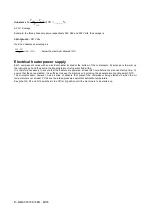
In a three-phase system, excessive unbalance between the phases causes overheating of the engine. The maximum
allowed voltage unbalance is 3%, calculated as follows:
Содержание EWAD E-SS Series
Страница 43: ...D EIMAC00708 16EN 43 76 Figure 18 Field Wiring Diagram...
Страница 75: ...D EIMAC00708 16EN 75 76...


