D
–EIMAC00708-16EN - 44/76
Operation
Operator’s responsibilities
It is important that the operator is appropriately trained and becomes familiar with the apparatus before operating the
machine. In addition to reading this manual, the operator must study the microprocessor operating manual and the wiring
diagram in order to understand startup sequence, operation, shutdown sequence and operation of all the safety devices.
During the machine’s initial startup phase, a technician authorized by the manufacturer is available to answer any
questions and to give instructions as to the correct operating procedures.
The operator is advised to keep a record of operating data for every installed machine. Another record should also be
kept of all the periodical maintenance and servicing activities.
If the operator notes abnormal or unusual operating conditions, he is advised to consult the technical service authorized
by the manufacturer.
Description of the machine
This machine, of the air-cooled condenser type, is made up of the following main components:
-
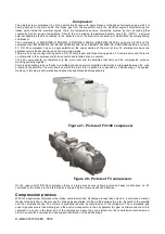
Compressor
: the state-of-the-art single-screw compressor of the Fr3100 or Fr3200 series is of the semi-hermetic
type and utilises gas from the evaporator to cool the engine and allow optimal operation under all foreseen load
conditions. The oil-injection lubrification system does not require an oil pump as its flow is ensured by the pressure
difference between delivery and intake. In addition to ensuring lubrification of ball bearings, oil injection seals the screw
dynamically thus ensuring the compression process.
-
Evaporator
: For EW AD E-SS/SL only. High-efficiency direct-expansion plate type; the evaporator is of ample size in
order to ensure optimum efficiency under all load conditions.
-
Condenser
:
Finned-pack type with internally microfinned tubes, that expand directly on the high -efficiency open fin.
The condenser batteries are provided with an undercooling section whi
ch, in addition to improving the machine’s overall
efficiency, compensates the thermal load variations by adapting the refrigerant load to every foreseen operating
condition.
-
Ventilator
:
High-efficiency axial type. Allows silent operation of the system, also during adjustment.
-
Expansion valve
:
The standard machine has a thermostatic expansion valve with an external equaliser.
Optionally, an electronic expansion valve can be installed, which is controlled by an electronic device called Driver that
optimises its operation. Use of the electronic expansion valve is recommended in case of prolonged operation at partial
loads with very low outdoor temperatures or if the machine is installed in variable flow rate systems.
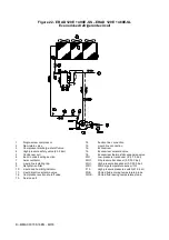
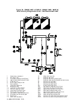
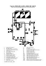
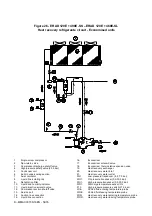
Description of the chilling cycle
ATTENTION
In the following schemas position of component are indicative.
In particular position of connections (water o refrigerant connection to external plant) may be different.
Refer to on board certified drawings for exact postion on specific unit.
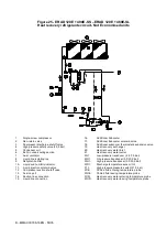
EWAD E-SS/SL
The low-temperature refrigerant gas from the evaporator is taken in by the compressor and crosses the electrical engine,
cooling it. It is subsequently compressed and during this phase the refrigerant mixes with the oil from the separator.
The high-pressure oil-refrigerant mixture is introduced into the oil separator, which separates it, the oil owing to a
pressure difference is sent once again to the compressor while the refrigerant that has been separated from the oil is
sent to the condenser.
Inside the condenser, the refrigerant fluid is evenly distributed to all the battery circuits; during this process it cools a fter
overheating and starts to condense.
The fluid condensed at saturation temperature travels through the undercooling section, where it yields further heat, thus
increasing cycle efficiency. The heat taken from the fluid during the de-overheating, condensation and undercooling
phase is yielded to the cooling air which is expelled at a higher temperature.
The undercooled fluid travels through the high-efficiency dehydration filter and then through the lamination organ which
launches the expansion process by means of a pressure drop, vaporising part of the refrigerant liquid.
After the expansion the low-pressure and low-temperature liquid-gas mixture, requiring much heat, that is introduced into
the evaporator.
After the liquid-vapour refrigerant has been evenly distributed in the direct-expansion evaporator tubes, it exchanges
heat with the water to be cooled, thus reducing its temperature, and it gradually changes state until evaporating
completely and then overheating.
Once it has reached the overheated-vapour state, the refrigerant leaves the evaporator and is once again taken i nto the
compressor and restarts the cycle.
Содержание EWAD E-SS Series
Страница 43: ...D EIMAC00708 16EN 43 76 Figure 18 Field Wiring Diagram...
Страница 75: ...D EIMAC00708 16EN 75 76...


