D
–EIMAC00708-16EN - 50/76
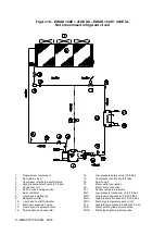
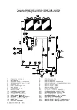
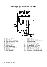
Description of the chilling cycle with heat recovery
With reference to stardard refrigerante cycle (both for chiller and condensing units), the high pressure refrigerant that has
been separated from the oil, before reaching the condenser coil, flows trough the recovery heat eexchanger, where it
dissipates the heat (from gas de-superheating and partial condensation) , warming the water which travels through the
exchanger. On leaving the exchanger the refrigerant fluid enters the condenser coil where it is completely condensed by
forced ventilation.
In not economised units, an additional subcooler is added on the liquid line, using evaporation of a small portion of liquid,
drained from the main liquid flow and expanded to suction pressure, to guarantee subcooling of refrigerant reaching the
expansion valve.
Controlling the partial recovery circuit and installation recommendations
The heat recovery system is not managed and/or controlled by the unit to match the heat demand from the plant; the unit
load is controlled from the chilled water demand and the heat not consumed by the recovery system is rejected in the
condenser coil..
The installer should follow the suggestions below for best system performance and reliability:
Install a mechanical filter at exchanger entrances
Install sectioning valves to exclude the exchanger from the hydraulic system during periods of inactivity or during system
maintenance.
Install a discharge tap to empty the heat exchanger, in the event that air temperature can be expected to fall below 0°C
during periods of inactivity of the machine.
Interpose flexible anti-vibration joints on recuperator water input and output piping, to keep transmission of vibrations,
and therefore of noise, to the hydraulic system as low as possible.
Do not load exchanger joints with the weight of recuperator piping. Hydraul ic joints of exchangers are not designed to
support their weight.
Should recovery water temperature be lower than ambient temperature, it is advised to switch off the recovery water
pump 3 minutes after having switched off the last compressor.
Содержание ERAD 120E-SL
Страница 43: ...D EIMAC00708 16EN 43 76 Figure 18 Field Wiring Diagram...
Страница 75: ...D EIMAC00708 16EN 75 76...


