background image

IM 1229-1 • INTELLIGENT EQUIPMENT 5 

www.DaikinApplied.com

r

emoval


and

 I

nsTallaTIon

 I

nsTruCTIons

r

emoval


and

 I

nsTallaTIon

 I

nsTruCTIons

Necessary Tools

•  Multimeter
•  #2 Phillips Screwdriver
•  #2 Flat Screwdriver
• 

5/16" Nut Driver

 WARNING

Electric shock hazard . Can cause personal injury or 

equipment damage .

Prior to replacing Intelligent Equipment hardware, power must 

be removed from the unit. This means removing power at the 

breaker panel serving the unit, and following proper lockout/

tagout  procedures  at  said  breaker  panel  for  the  duration  of 

the install. Power should not be reapplied until all electrical 

interconnections have been made and verified.
This  equipment  must  be  properly  grounded.  Connections 

and service to the MicroTech III Air Handling Unit Controller, 

Machine-to-Machine  Gateway  and  Energy  Management 

Module must be performed only by personnel knowledgeable 

in the operation of the equipment being controlled.

 CAUTION

Static sensitive components . Can cause equipment 

damage .

Discharge  any  static  electrical  charge  by  touching  the  bare 

metal inside the control panel before performing any service 

work. Never unplug cables, circuit board terminal blocks, or 

power plugs while power is applied to the panel.

 CAUTION

Sharp  edges  on  sheet  metal  and  fasteners  can  cause 

personal injury. This equipment must be installed, operated, 

and  serviced  only  by  an  experienced  installation  company 

and fully trained personnel.

Removal

Disconnecting Existing Wiring 

Interconnections

Prior to replacing the M2M Gateway, power must be removed 

from the unit. Power must be removed at the breaker panel 

serving the unit, and proper lockout/tagout procedures should 

be followed for the duration of the install. After removing 

unit power at the breaker panel, the installer must verify the 

absence of power at the unit using a multimeter. Only if power 

has been verified absent, should the technician continue the 

replacement process.

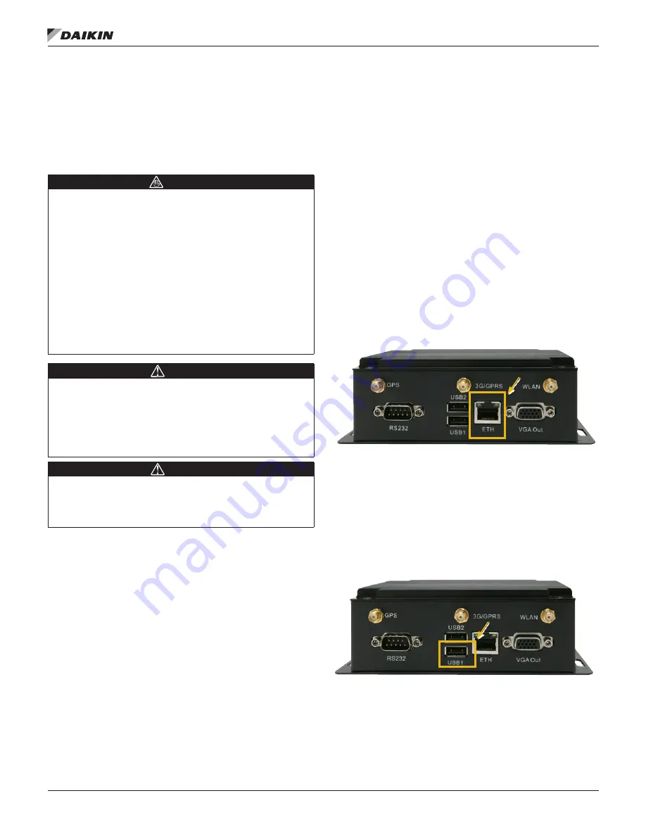
M2M Connection to MTIII 

The M2M Gateway is connected to the MicroTech III unit 

controller via Ethernet. Disconnect the Ethernet Patch cable 

from the M2M port marked, “ETH” (

Figure 1

).

Figure 1: ‘ETH’ Port       

M2M Connection to EMM

The M2M Gateway is connected to the Energy Management 

Module (EMM) via USB. Remove the USB cable connection 

from the M2M port marked, “USB1” (

Figure 2

).

Figure 2: USB Connection          

Содержание DPS

Страница 1: ...tion and Maintenance Manual IM 1229 1 Group Controls Part Number 910159718 Date November 2015 Replacement Intelligent Equipment Gateway Commercial Rooftop Models DPS and MPS Applied Rooftop Models RDS...

Страница 2: ...Machine to Machine M2M Gateway 4 Unpacking 4 Material shipped loose 4 Removal and Installation Instructions 5 Necessary Tools 5 Removal 5 Disconnecting Existing Wiring Interconnections 5 Installation...

Страница 3: ...a hazardous situation which will result in death or serious injury if not avoided WARNING Warnings indicate potentially hazardous situations which can result in property damage severe personal injury...

Страница 4: ...and CRM data to a user device smart phone tablet etc via wireless Wi Fi cellular or local area network LAN connection This manual contains instructions specific to replacing an existing machine to ma...

Страница 5: ...inside the control panel before performing any service work Never unplug cables circuit board terminal blocks or power plugs while power is applied to the panel CAUTION Sharp edges on sheet metal and...

Страница 6: ...the M2M Gateway receptacle marked Power Input Figure 3 Figure 3 M2M Power Input Antenna and Ethernet Connections Depending on the application the M2M Gateway could be connected to the cloud via cellu...

Страница 7: ...of the existing Gateway on the mounting bracket The new M2M Gateway must be installed in the same orientation Remove the existing Gateway by unscrewing the 5 16 head sheet metal screws located at the...

Страница 8: ...nter the unique password that was provided with the Gateway hardware and press ENTER c This opens the Gateway home page 3 Click the System tab Figure 7 a Select the Settings tab b Under Time Zone veri...

Страница 9: ...IM 1229 1 INTELLIGENT EQUIPMENT 9 www DaikinApplied com System Set Up Figure 7 System Tab Figure 8 Time Updated to Time Zone Figure 9 Keypad Controls Figure 10 Date Time Schedules Menu...

Страница 10: ...ore information on how to change your computer s IP settings consult the Operating System s Help files d Temporarily disable the wireless adapter s on the computer as these may prevent accessing the H...

Страница 11: ...IM 1229 1 INTELLIGENT EQUIPMENT 11 www DaikinApplied com System Set Up Figure 11 M2M Gateway Home Page Figure 12 Verify Cellular Signal Strength...

Страница 12: ...ay home page Figure 13 4 If the M2M Gateway will be using DHCP skip to step 6 If the M2M Gateway will be using a Static IP address go to step 5 5 Click the Network tab a Under wlan0 Configuration Figu...

Страница 13: ...IM 1229 1 INTELLIGENT EQUIPMENT 13 www DaikinApplied com System Set Up Figure 13 M2M Gateway Home Page Figure 14 Wireless LAN Configuration...

Страница 14: ...IM 1229 1 INTELLIGENT EQUIPMENT 14 www DaikinApplied com System Set Up Figure 15 Wireless Configuration Screen Figure 16 Wireless Signal Strength...

Страница 15: ...to match the subnet c Navigate to your laptop s Local Area Connection settings screen and change the IP subnet mask to 255 255 0 0 and the IP address to be compatible with the default M2M Gateway IP a...

Страница 16: ...this can take as much as two minutes 16 Confirm that ICMP host of wan interface is still set to disable a If so go to step 17 b If not set to disable c Click Save changes button i IMPORTANT Allow the...

Страница 17: ...IM 1229 1 INTELLIGENT EQUIPMENT 17 www DaikinApplied com System Set Up Figure 18 WAN Configuration Settings Figure 19 Add New Interface Selection...

Страница 18: ...IM 1229 1 INTELLIGENT EQUIPMENT 18 www DaikinApplied com System Set Up Figure 20 M2M Gateway Home Page Figure 21 WAN Configuration Settings...

Страница 19: ...magnetic base Check antenna connection to WLAN connection on Gateway Check signal strength through WebIF Verify Wi Fi IP addressing ESSID and login credentials match customer supplied Wireless LAN re...

Страница 20: ...nt to its standard terms and conditions of sale including Limited Product Warranty Consult your local Daikin Applied representative for warranty details To find your local Daikin Applied representativ...

Отзывы: