IM
1133-C
DIII-NET COMMUNICATION GATEWAY
7
www.DaikinApplied.com
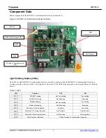
Component Data
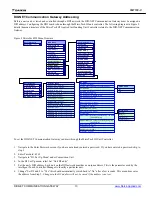
Major components of the DIII-NET Communication Gateway are labeled in .
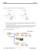
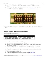
Figure 2, DIII-NET Communication Gateway Installed
Light Emitting Diodes (LEDs)
The LED’s on the DIII-NET Communication Gateway are used to indicate either the DIII-NET Communication Gateway is
working correctly or there is a fault. A description of what each of the LEDs being energized or de-energized means is listed in
Table 1.
Table 1,
LED’s
LED
Function
OFF
ON
H1P
DIII-NET Sending
Not Transmitting
Transmitting
H2P
DIII-NET Receiving
Not Receiving
Receiving
H3P
Modbus Sending
Not Transmitting
Transmitting
H4P
Modbus Receiving
Not Receiving
Receiving
H5P
MicroTech III Fault Indication
No Faults
Fault Alarm
H6P
MicroTech III Problem Indication
No Problems
Problem Alarm
H7P
MicroTech III Warning Indication
No Warnings
Warning Alarm
HAP
Micro Processor Operation
800ms Flashing Period Indicates Operation
LED’s H1P through H7P.
DS1
DIII
Communication Port
Modbus Communication
Port
Part Number
24VAC
DS2


