IM 817-4
Page 25 of 60
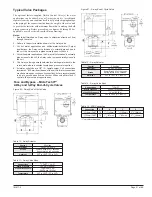
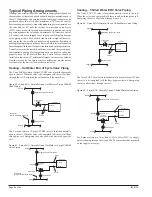
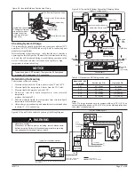
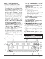
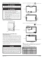
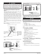
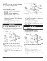
Typical Water Coil Piping - EOC Valve Piping
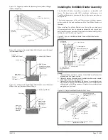
Figure 70 - Face and Bypass With 3-way End-of-Cycle Valve
(Piping Within Unit End Compartment)
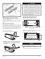
Figure 71 - Face and Bypass With 3-way End-of-Cycle Valve
(Piping Outside Unit End Compartment)
2
3
4
5
6
7
8
15
1
S5 Sensor
S5 Sensor
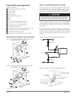
Table 20 - Descriptions
Three-way End of Cycle control valve (
Daikin
)
Coil air vent (Daikin)
Coil drain (Daikin)
Shutoff valve (Others)
Balancing shutoff valve(s) (Others)
Supply
Return
Unions (Others)—Must disconnect below floor line
Two-way, End of Cycle two-position valve (Daikin)
Union: Half attached to coil, half attached to valve
Modulating control valve (Daikin)
All piping, fittings and unions by others (not Daikin) except as noted
Steam check valve and pressure equalizing line (Daikin)
Float and thermostatic steam trap (Others)
Supply and return coil connection and stub-up unions by others
2
1
3
6
4
5
7
8
15
14
13
12
11
10
9
Typical Piping Arrangements
Steam – Typical Modulating Valve Piping
T h e o p t i o n a l f a c t o r y s u p p l i e d D a i k i n M i c r o Te c h
I I ™
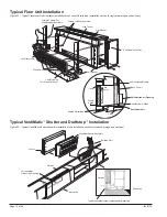
2-way Modulating steam valve is furnished normally open to the coil.
When the valve is de-energized (off) there is full flow through the coil.
Energizing the valve reduces the steam flow in a modulating fashion.
Refer to the arrow on the modulating valve body to determine
the direction of flow. If the valve is mounted improperly, the unit
will not operate properly and damage to the valve may result.
The valve should be installed so that there is a 2" (51mm) minimum
clearance to remove the actuator form the valve body. Provide unions
for removal of unit coil and/or control valve as a future service
consideration.
Steam connections may be same end as cooling coil connections, but
are recommended to be opposite end to facilitate piping. When using
MicroTech II controls, they must be opposite end. The modulating
valve accessory must be field installed on the unit for which it was
selected.
Return
Shutoff Valve
Shutoff Valve
Supply
Return
Supply
Unit Coil
Equalizing Line
Steam Trap
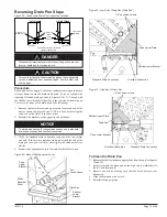
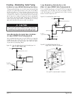
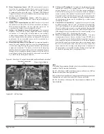
Figure 73 - Same End Connections – Model AV 68/69 Coils
Control Valve: Install On
Center Coil Connection
Vacuum Breaker
(by Daikin)
Vacuum Breaker Tube
(by Daikin)
Steam Trap (by Others)
1⁄4" Flare by 1⁄2" MPT
Half-Union and 1⁄4" Flare
(by Daikin)
Tee (by Others)
Union
Figure 72 - Typical 2-Way Steam Modulating Valve Piping
2
1
3
4
5
15
6
15
15
7
CAUTION

