40
Maintenance
Tr
oub
leshooting
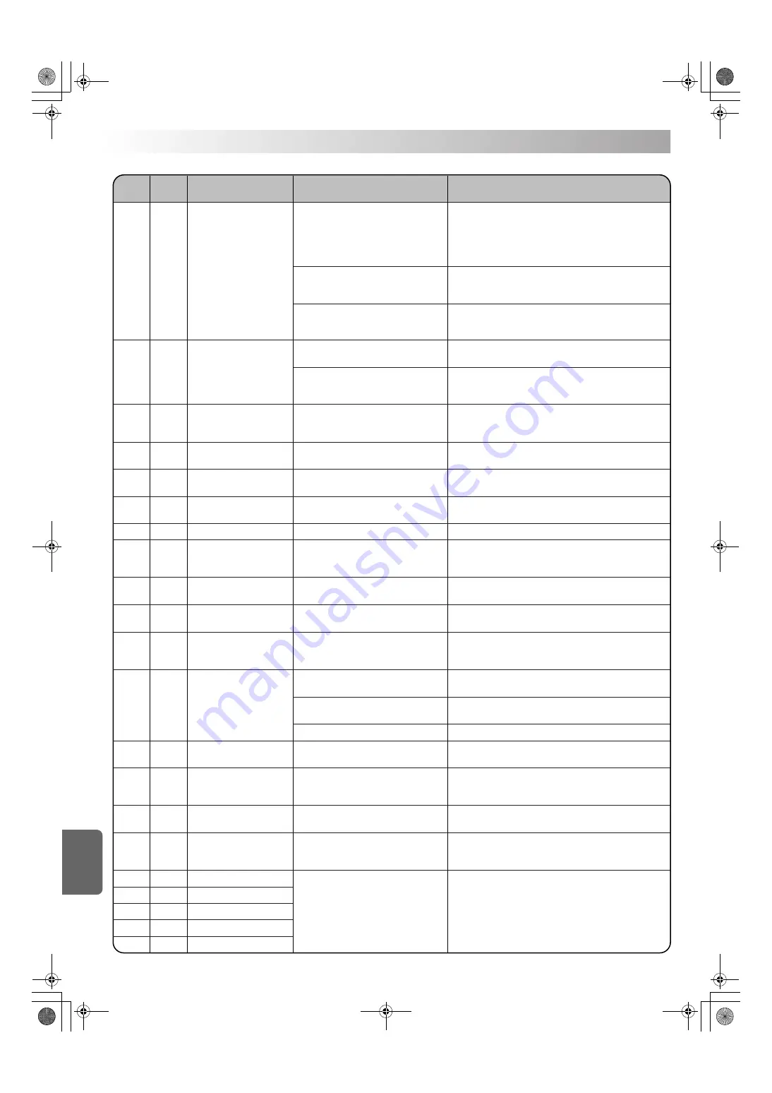
Alarm
code
Alarm
level
Description
Cause
Corrective action
Pump outlet oil temperature
thermistor error
Oil temperature thermistor error
(Th2: Outlet oil temperature thermistor)
(Th4: Inlet oil temperature thermistor)
Discharge pipe temperature
thermistor error
EV valve outlet temperature
thermistor error
Condenser temperature
thermistor error
Inverter/compressor error
INV-temperature control CPU
communication error
Electrical equipment box
temperature thermistor error
Radiator fin temperature
thermistor error
Gas shortage
Power supply reverse-phase
connection
Momentary power failure or
voltage drop
Other system communication error
(Slave communication error)
System failure
(EEPROM error)
Optional protection device is
activated. (OP2)
Temperature range warning 1
Temperature range warning 5
JE
1
Inlet oil temperature is higher
than 60˚C.
FH
2
JH
2
J3
2
J5
2
J6
2
L0
2
LC
2
P3
2
P4
2
U0
2
U1
1
U2
2
U9
2
UH
2
UJ
1 or 2
1E
–
Temperature range warning 2
2E
–
Temperature range warning 3
3E
–
Temperature range warning 4
4E
–
5E
–
1) The pump outlet oil temperature thermistor
is disconnected or short-circuited.
Check the wiring of the relevant thermistor.
3) The unit is running under capacity
suppressing control, because the standard
temperature (room temperature: 35˚C, oil
temperature: 35˚C) has been exceeded.
If the standard temperature is exceeded, the cooling capacity
becomes smaller than the nominal capacity, because the unit
runs under capacity suppressing control.
Make sure that the cooling capacity of the Oil Cooling Unit is
larger than the main machine heating value throughout the oper-
ating temperature range.
4) Temperature control is disabled because
the unit is operated in Mode 9 (capacity
direct designation mode).
Select an appropriate operation mode.
(The capacity direct designation mode does not execute temper-
ature feedback control.)
If the exhaust air temperature is almost equal to the room
temperature regardless of the compressor operation, it is possible
that the refrigerant gas has leaked. Contact DAIKIN Contact Center.
Connect a dummy connector to CN8.
Check the wiring of the relevant thermistor.
Check the wiring of the relevant thermistor.
Check the wiring of the relevant thermistor.
Check the wiring of the relevant thermistor.
Repair the refrigerant pipe, and refill refrigerant.
Exchange any phase of the power supply wiring.
Contact DAIKIN Contact Center.
Replace the control board.
Check the preset warning condition.
Check the wiring of the relevant thermistor.
Replace the control board or compressor.
Identify the thermistor that indicates the error in the monitor
mode on the operation panel (“99.9” is displayed), and check
the sensor wiring.
Replace the control board, or improve the power supply
environment. (Take noise suppressing measures.)
Make sure that the L3 phase is properly connected to the
power supply terminal block.
Check the condition detected with the relevant protection device.
Make sure that the power supply voltage conforms to the rating.
Check for instantaneous voltage drop at startup of peripheral equipment.
Make sure that the slave communication line is properly connected.
(This error occurs only when the slave does not make response
in master-slave communication.)
1) The oil temperature thermistor required
for control is disconnected or short-
circuited.
1) The discharge pipe temperature thermistor
is disconnected or short-circuited.
1) The EV valve outlet temperature thermistor
is disconnected or short-circuited.
1) The condenser temperature thermistor is
disconnected or short-circuited.
1) Communication failure between the
temperature control microprocessor and
the inverter microprocessor.
1) The electrical equipment box temperature
thermistor is disconnected or shortcircuited.
1) The radiator fin temperature thermistor is
disconnected or short-circuited.
1) The power supply voltage is lower than
approx. 170 V.
1) An error occurred in communication with
a slave.
1) The parameter stored in the control board
is invalid.
1) The optionally-connected protection device
(or factory-connected device, if it is
incorporated in the unit) has been activated.
1) The monitor temperature has exceeded
the preset temperature. (It does not mean
a fault of the Oil Cooling Unit.)
1) The refrigerant piping is damaged by
excess vibration during transportation,
resulting in refrigerant gas leak.
1) The compressor or inverter has a fault.
1) The power supply is connected in reverse
phase.
2) The L3 phase is open.
5) The refrigerant gas has leaked.
3) The fuse in the control board has blown.
2) For the models without pump outlet oil
temperature thermistor:
Dummy connector is not connected.
PIM00116C_EN.fm 40 ページ 2008年9月29日 月曜日 午前11時51分
Содержание AKZ8 Series
Страница 2: ...PIM00116C_EN fm 0...
Страница 43: ...41 PIM00116C_EN fm 41...


