background image

48


DAIHEN Corporation


4-1, Koyocho-nishi, Higashinada-ku, Kobe, Hyogo 658-0033, Japan 

Phone: +81-78-275-2006, Fax: +81-78-845-8159 


DAIHEN Inc.


1400 Blauser Drive Tipp City, Ohio 45371, USA 

Phone: +1-937-667-0800, Fax: +1-937-667-0885 


DAIHEN MEXICO S.A. de C.V.


Mineral de Valenciana 645, Edif. F3y4 Centro de Negocios Santa Fe  

Puerto Interior Silao de la Victoria, Gto. CP 36275 

Phone: +52-472-748-9435 


OTC DAIHEN EUROPE GmbH


Krefelder Strasse 677, D-

41066 Mönchengladbach, Germany 

Phone: +49-2161-694970, Fax: +49-2161-6949761


DAIHEN VARSTROJ welding cutting and robotics d.d.


Industrijska ulica 4, 9220 Lendava - Lendva, Slovenija 

Phone: +386-25-788-826, Fax: +386-25-751-277 


OTC Industrial (Shanghai) Co., Ltd.


6F, Building B,ORIENTO Plaza, 388 North Fuquan Road,  

Changning District, Shanghai, China 200335 

Phone: +86-21-5882-8633, Fax: +86-21-5882-8846 


 OTC (Taiwan) Co., Ltd.


2F No.153, Huanbei Rd., Chung Li City, Taoyuan Hsien, Taiwan 

Phone: +886-3-461-3962, Fax: +886-3-434-2394 


OTC DAIHEN Asia Co., Ltd.


23/

43, 16th F1.Sorachai Building, 23 Soi 63 Sukhumvit Road,  

Klongtonnua, Wattana, Bangkok 10110, Thailand 

Phone: +66-2-714-3201, Fax: +66-2-714-3204 


OTC DAIHEN INDIA PVT.LTD.


V. M. TOWER, Plot No. 54A, Ground Floor Unit-1,  

Sector-18, Gurugram-122015 Haryana, India 

Phone:+91 124-4239368, +91 124-4239364 


PT.OTC DAIHEN INDONESIA


Blok G1A-20, Jl. Kenari ll, Delta Silicon V, 

Lippo Cikarang Industrial Park, Bekasi 17550 Indonesia 

Phone:+6221-2957-7566, Fax:+6221-2957-7567 


DAIHEN Korea Co., Ltd.


85, Hyeongoksandan-ro, Cheongbuk-myeon, Pyeongtaek-si, Gyeonggi-do, 451-831,Korea. 

Phone: +82-31-686-7459, Fax: +82-31-686-7465 


Upon contact, advise MODEL and MANUAL NO.


210901 

Содержание OTC CM-0401-D

Страница 1: ...OWNER S MANUAL WIRE FEEDER MODEL CM 0401 D Ensure to read this instruction manual thoroughly for safe and proper use of the product MANUAL No 632189 1 2023 11 EN...

Страница 2: ...Y PERFORMING INCHING OPERATION 23 8 DIGITAL CONTROL PANEL 24 8 1 SETTING INTERNAL FUNCTIONS 24 8 2 TROUBLESHOOTING 25 8 2 1 ACTION IN CASE OF ERROR 25 8 2 2 ACTION IN CASE OF TROUBLE 25 9 MAINTENANCE...

Страница 3: ...prevent from various hazards that cause serious injury and damages Indication and explanation for the symbols are as follows Symbols Explanation WARNING WARNING gives information regarding possible pe...

Страница 4: ...art technology and according to recognized safety standards If used incorrectly or misused however it can cause injury or death to the operator or a third party damage to the device and other material...

Страница 5: ...witch is ON Do not wrap cables around your body When the wire feeder is not in use or the work is interrupted for a long time shut off the power of all units Blow dry air to parts periodically to remo...

Страница 6: ...uisher nearby Be aware that welding on a ceiling floor bulkhead or partition can ignite a hidden fire Do not weld on closed containers such as tanks or drums Connect base metal side cable as close to...

Страница 7: ...G CYLINDER can explode if damaged A shielding gas cylinder contains high pressure gas If damaged a cylinder can explode Since gas cylinders are normally part of the welding process be sure to treat th...

Страница 8: ...ngers hair or clothes are put near the fan s rotating parts or wire feeder s feed roll injuries may occur Do not use this equipment if the case and the cover are removed When the case is removed for m...

Страница 9: ...feeder Accessory Description Specification Quantity MANUAL CM 0401 D 1 4 NAMES OF PARTS Gas supply inlet 6 1 Water connection Water out Water in Wire reel hub Frame Water connection Water out Water in...

Страница 10: ...lation Adequately ventilate or wear a gas mask when using the welding machine in a tank a boiler a hold of a ship because heavier gas such as carbon dioxide or argon gases are drifting there When usin...

Страница 11: ...wer source by turning off the line disconnect switch in the power box to avoid an electric shock before grounding the welding power source or base metal and connecting the cables or hoses Do not use a...

Страница 12: ...12 6 1 CONNECTION FLOW CHART 1 1 2 1 2 3 3 4 4 5 5 6 7 8 6 7 8...

Страница 13: ...s hose after fixing to the stand as physical injuries may result from the gas cylinder toppling over Attach a proper gas regulator to a gas cylinder Failure to do so may result in physical injuries Th...

Страница 14: ...r is firmly attached If the connector is not fully inserted there may be a risk of product damage How to connect the connection cables Connect the connection cables following the procedure shown below...

Страница 15: ...se metal and connecting the cables or hoses After connecting the cables cover the power source with the cover or case When using the welding machine in such a humid environment as construction site on...

Страница 16: ...UTION Ensue that the torch connector is firmly attached If the connector is not fully inserted there may be a risk of fire burns and product damage How to connect the welding torch Connect the welding...

Страница 17: ...isable normal wire feed or deform the wire resulting in improper welding Procedure for checking feed roll Check whether feed rolls suitable for the wire size are mounted following the procedure shown...

Страница 18: ...18 Lock gear carrier...

Страница 19: ...re is set on the wire reel shaft fully tighten the cap to prevent falling In case a breakage crack or deformation is found in the wire reel shaft or cap do not use but replace it Fitting of Wire Fit t...

Страница 20: ...20...

Страница 21: ...the wire pressure and straightener Set to the proper wire pressure for the wire type by turning the pressure handle The numeral on the pressure scale set with the right pressure handle should be corr...

Страница 22: ...he wire reel shaft as illustrated below with care placed to the mounting direction Mount the brake disk to the wire reel shaft as illustrated below with care placed to the mounting direction In the ev...

Страница 23: ...way from the end of the tip Wire feed rate can be adjusted with the parameter adjusting knob on the operating panel For more details check ARXIS welding power source owner s manual Chapter 5 4 WARNING...

Страница 24: ...24 8 DIGITAL CONTROL PANEL 8 1 SETTING INTERNAL FUNCTIONS Check ARXIS welding power source owner s manual Chapter 6 2...

Страница 25: ...elding power source Set the CAN ID of the internal function F43 to 1 The internal functions F79 are not set properly Confirm that the internal functions F79 are set properly The welding power source s...

Страница 26: ...reak in parts and sheet metals inside wire feeder 9 Is there not portion of wiring inside wire feeder that is beginning to break 10 Is there no loosening of parts fixing 11 Is there no connecting part...

Страница 27: ...27 Schematic Diagram Legend M1 Motor L1 L2 Ferrite core S1 Torch switch X1 7 Connector X8 Central connector X9 10 CAN Connector Y1 Gas valve W1 Power cable...

Страница 28: ...ow the procedures below when replacing the outlet guide 1 Open the side door 2 Bring down the pressure handle then raise the pressure roll holder 3 Rewind the wire to reel 4 Remove the torch from the...

Страница 29: ...29 6 Put a new outlet guide through the torch connection port with careful attention paid to the direction of the outlet guide 7 Reassemble the wire feeder following the reverse procedure...

Страница 30: ...brush Target for life and replacement of feed motor The life of the feeding motor is approximately 2 000 to 3 000 hours In addition the life varies with the load conditions and ambient temperature Wh...

Страница 31: ...31 9 4 REPLACE THE CENTER GUIDE Replace the center guide following the procedure shown below...

Страница 32: ...632137 INTERMEDIATE CABLE ARXIS W 5m 632138 INTERMEDIATE CABLE ARXIS W 10m 632139 INTERMEDIATE CABLE ARXIS W 15m 10 2 INTERMEDIATE CABLE GAS COOLED 632179 INTERMEDIATE CABLE ARXIS G 1m 632180 INTERME...

Страница 33: ...code Description Q ty Part no Remarks 1 631853 FRAME ASSY 1 Chapter 11 2 2 631894 HOUSING ASSY 1 Chapter 11 3 3 631895 DRIVE MODUL 1 Chapter 11 4 4 631896 FRONT PANEL ASSY 1 Chapter 11 5 5 631897 REA...

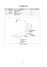
Страница 34: ...2FRAME ASSY No Order code Description Q ty Remarks 1 631827 SA METAL BASE FRAME 1 2 631292 HANDLE GRIP 1 3 631291E1 HINGE 1 4 631851 SA ROTATING CARRIER 1 5 SCREW M6X12 4 Figure 2 Frame assy 2 3 1 4...

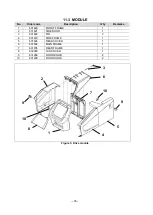
Страница 35: ...31820 FRONT FRAME 1 2 631821 SIDE DOOR 1 3 631822 PIN 2 4 631823 SIDE FRAME 1 5 631824 REAR COVER 1 6 631834 MAIN FRAME 1 7 631835 REAR FRAME 1 8 632083 LCD COVER 1 9 631289 DOOR KNOB 2 10 631290 DOOR...

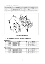
Страница 36: ...der code Description Q ty Remarks 1 631857 SA METAL FRAME 1 2 631968 WIRE FEEDER SF ST4 1 3 631969 FEED MOTOR 1 4 631884 TORCH CONNECTION 1 5 604826 CONNECTION BLOCK 1 6 606783 BASE FOR TIES 1 Figure...

Страница 37: ...flat rool Bottom feed rool No Order code Description Q ty Remarks 1 632192 FEED ROLL 0 6 0 8 4 For steel V type groove 1 632193 FEED ROLL 0 8 1 0 4 For steel V type groove 1 632194 FEED ROLL 1 0 1 2 4...

Страница 38: ...roove 1 2 632007 FEED ROLL 1 0 1 2 TWIN 4 For aluminum U type groove 1 2 632008 FEED ROLL 1 2 1 6 TWIN 4 For aluminum U type groove 1 2 632009 FEED ROLL 1 6 2 4 TWIN 4 For aluminum U type groove 1 2 6...

Страница 39: ...s 1 632206 WIRE GUIDE 0 6 1 6 1 2 012535 HOSE 5 X 2 5 1 Order unit m 3 692952 HOSE CLAMP 11 3 1 Figure 6 Torch connection OPTIONAL Wire guide No Order code Description Q ty Remarks 1 632206 WIRE GUIDE...

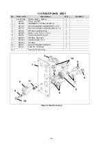
Страница 40: ...ETAL FRONT PANEL 1 2 631886 SA METAL FRONT COVER 3 631802 CENTRAL CONNECTOR HOUSING 1 4 631756 QUICK CONNECTOR RED NW 5 G 1 4 1 5 631757 QUICK CONNECTOR BLUE NW 5 G 1 4 1 6 631794 FITTING KQ2E08 G02A...

Страница 41: ...R RED NW 5 G 1 4 1 5 631757 QUICK CONNECTOR BLUE NW 5 G 1 4 1 6 631794 FITTING KQ2E08 G02A 2 7 631885 SEAL 13 0 X 18 0 X 1 5 CU 2 8 696484 GAS SOLENOID VALVE 1 9 680820 FITTING 6R12X25 1 10 681089 HOS...

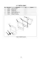
Страница 42: ...iption Q ty Remarks 1 632882 LCD T070WTRZ1 1 2 631878 METAL PLATE 1 3 631868 FRONT FOIL 1 4 631844 KNOB 7136062 1 5 631845 KNOB COVER B7536109 1 6 632190 BACK COVER assy 1 7 631275 GROMET P30304W03 1...

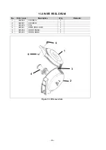
Страница 43: ...IRE REEL DRUM No Order code Description Q ty Remarks 1 632090 COVER A 1 2 632091 COVER B 1 3 631285 PIN 1 4 601591 WIRE REEL HUB 1 5 631289 DOOR KNOB 1 6 631290 DOOR HOOK 1 Figure 10 Wire reel drum 6...

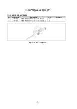
Страница 44: ...11 9 OPTIONAL ACCESSORY 11 9 1 WIRE STRAIHTENER No Order code Description Q ty Remarks 1 632094 WIRE STRAIGHTENER SET For Steel 1 2 632095 WIRE STRAIGHTENER SET For aluminum 1 Figure 11 Wire straighte...

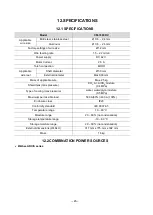
Страница 45: ...ameter Max 300 mm Mass of applicable wire Max 25 kg Shield Gas max pressure CO2 Ar ArCO2 mixture 0 4 MPa Type of cooling max pressure water water glycol mixture 0 5 MPa Maximum permissible load 500 A...

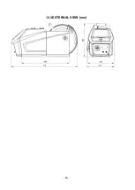
Страница 46: ...46 12 3EXTERNAL VIEW mm...

Страница 47: ...47...

Страница 48: ...ORIENTO Plaza 388 North Fuquan Road Changning District Shanghai China 200335 Phone 86 21 5882 8633 Fax 86 21 5882 8846 OTC Taiwan Co Ltd 2F No 153 Huanbei Rd Chung Li City Taoyuan Hsien Taiwan Phone...

Отзывы:

Похожие инструкции для OTC CM-0401-D