


Dahua Network Camera Web 3.0 Operation Manual
132
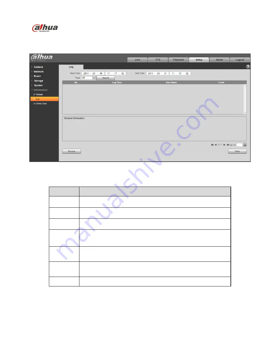
5.6.2 Log
Here you can view system log. See
Figure 5-120
.
Figure 5-120
Please refer to the following sheet for log parameter information.
Parameter
Function
Start time
Set the start time of the requested log. (The earliest time is 2000/1/1)
End time
Set the end time of the requested log. (The latest time is 2037/12/31)
Type
Log type.
Search
You can select log type from the drop down list and then click search
button to view the list.
You can click the stop button to terminate current search operation.
Log
information
You can select one item to view the detailed information.
Clear
You can click this button to delete all displayed log files. Please note
system does not support clear by type.
Backup
You can click this button to backup log files to current PC.
5.6.3 Online User
The online user interface is shown as in
Figure 5-121
.
Here you can view current online user, group name, IP address and login time.
Содержание Network Camera Web 3.0
Страница 24: ...Dahua Network Camera Web 3 0 Operation Manual 16 Figure 3 7 ...
Страница 53: ...Dahua Network Camera Web 3 0 Operation Manual 45 Figure 5 17 Figure 5 18 ...
Страница 54: ...Dahua Network Camera Web 3 0 Operation Manual 46 Figure 5 19 Figure 5 20 ...
Страница 121: ...Dahua Network Camera Web 3 0 Operation Manual 113 Figure 5 89 Figure 5 90 ...
Страница 141: ...Dahua Network Camera Web 3 0 Operation Manual 133 Figure 5 121 ...


