383
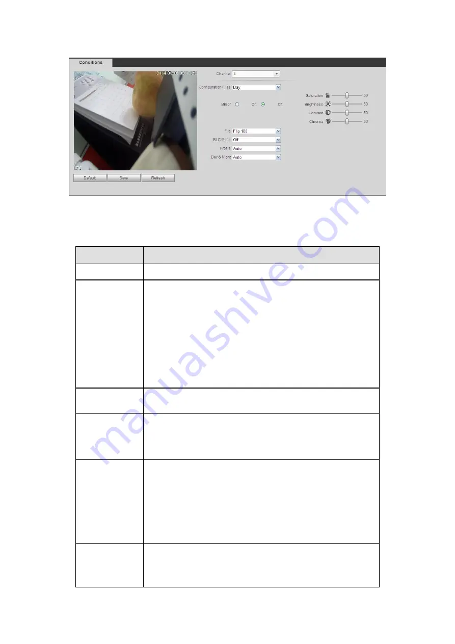
Figure 5-20
Please refer to the following sheet for detailed information.
Parameter
Function
Channel
Please select a channel from the dropdown list.
Cable type
It is to set the cable type of the corresponding analog channel.
When the setup here matches the actual cable you are using,
you can get the best image effect. The default setup is
COAXIAL.
COAXIAL: When the corresponding channel is using
coaxial cable, please select COAXIAL.
UTP: When the corresponding channel is using UTP cable,
please select UTP. Usually we recommend 10Ohm UTP
cable.
Period
It divides one day (24 hours) to two periods. You can set
different hue, brightness, and contrast for different periods.
Hue
It is to adjust monitor video brightness and darkness level. The
default value is 50.
The bigger the value is, the large the contrast between the bright
and dark section is and vice versa.
Brightness
It is to adjust monitor window brightness. The default value is 50.
The larger the number is , the bright the video is. When you
input the value here, the bright section and the dark section of
the video will be adjusted accordingly. You can use this
function when the whole video is too dark or too bright. Please
note the video may become hazy if the value is too high. The
value ranges from 0 to 100.The recommended value ranges
from 40 to 60.
Contrast
It is to adjust monitor window contrast. The value ranges from 0
to 100. The default value is 50.
The larger the number is, the higher the contrast is. You can use
this function when the whole video bright is OK but the contrast
Содержание HCVR2108C-S2 Series
Страница 1: ...Dahua HDCVI Standalone DVR User s Manual Dahua HDCVI Standalone DVR User s Manual V1 8 2 ...
Страница 11: ...x APPENDIX F COMPATIBLE WIRELESS MOUSE LIST 479 APPENDIX G EARTHING 480 ...
Страница 291: ...278 Figure 4 72 Figure 4 73 ...
Страница 322: ...309 Figure 4 105 Figure 4 106 ...
Страница 323: ...310 Figure 4 107 Figure 4 108 ...
Страница 339: ...326 Figure 4 125 Figure 4 126 ...
Страница 340: ...327 Figure 4 127 Figure 4 128 ...
Страница 341: ...328 Figure 4 129 Figure 4 130 ...
Страница 344: ...331 Figure 4 134 Figure 4 135 ...
Страница 351: ...338 Figure 4 145 Figure 4 146 4 11 4 1 2 2Trigger Snapshot ...
Страница 353: ...340 Figure 4 148 Figure 4 149 4 11 4 1 2 3Priority ...
Страница 370: ...357 Figure 4 170 For digital channel the interface is shown as below See Figure 4 171 Figure 4 171 ...
Страница 384: ...371 Figure 4 188 ...
Страница 402: ...389 Figure 5 26 5 8 2 Network 5 8 2 1 TCP IP The single Ethernet port interface is shown as in Figure 5 27 ...
Страница 419: ...406 Figure 5 55 Figure 5 56 ...
Страница 432: ...419 Figure 5 71 Figure 5 72 ...
Страница 439: ...426 Figure 5 81 Figure 5 82 Figure 5 83 Please refer to the following sheet for detailed information ...
Страница 482: ...469 448K 196M 512K 225M 640K 281M 768K 337M 896K 393M 1024K 450M 1280K 562M 1536K 675M 1792K 787M 2048K 900M ...


