6
2.4.2.2 Cable Connection
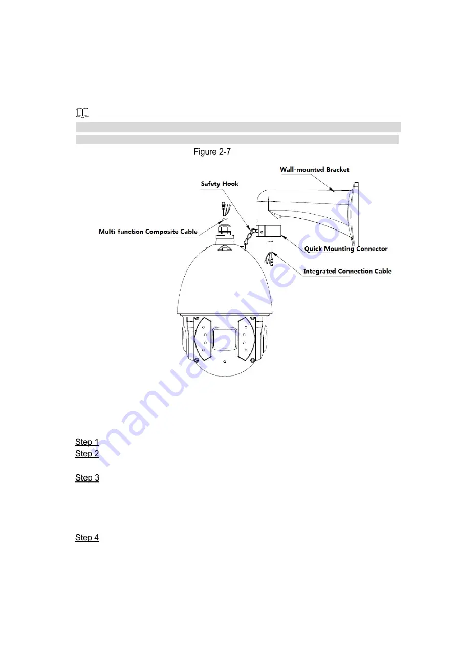
Buckle the safety hook of the speed dome on the quick mounting connector, and connect the
cables reserved on the wall-mounted bracket with the corresponding cables of the speed
dome as you need. Then twine the cable connection with insulated rubber tape to ensure
waterproof. See Figure 2-15.
Make sure the wire diameter of the cable connected to RS-485 control cable is not too big.
Otherwise, the control effect might be bad. See Appendix 2 for details about RS-485 cable.
Cable connection
2.4.2.3 Alarm Cable Connection
To connect alarm cables and configure alarm settings, do the following:
Connect alarm input device to the ALARM_IN and ALARM_GND of the cables.
Connect alarm output device to the ALARM_OUT and ALARM_COM of the cables.
Alarm output is the relay switch output.
Enter the web interface of the speed dome, and set the corresponding alarm input and
output by selecting
Setting > Event > Alarm Setup
. The alarm input on web interface
is corresponding to the alarm input of the cables. Set the corresponding NO and NC
output according to the high/low level signal generated by alarm input device when
alarm triggers.
Set the alarm output of cables on web interface.
Содержание 6AL445XANR
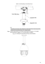
Страница 16: ...8 Installation finished...
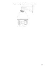
Страница 19: ...11 Installing the speed dome with wall mounted bracket...
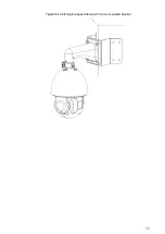
Страница 25: ...17 Installing the speed dome with corner mounted bracket...
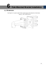
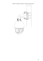
Страница 29: ...21 Installing the speed dome with pole mounted bracket...
Страница 30: ...22...


