Quick Start Guide
2
No.
Port name
Description
5
Alarm I/O
Includes alarm signal input and output ports, the number of
I/O ports might vary on different devices. For detailed
information, see Table 1-2.
Table 1-2 Description of alarm I/O port
Port Name
Description
ALARM_IN
Receives the switch quantity signal of external alarm sources.
Connect different alarm input devices to the same ALARM_IN_GND
port.
ALARM_IN_GND
ALARM_OUT
Outputs alarm signal to alarm devices.
When the camera is being connected to an alarm device, only the
ALARM_OUT port and ALARM_OUT_GND port with the same number
can be used together.
ALARM_OUT_GND
1.2 Connecting Alarm Input/Output
The camera can connect to external alarm input/output devices through the digital input/output
port.
Alarm input/output is available on select models.
Step 1
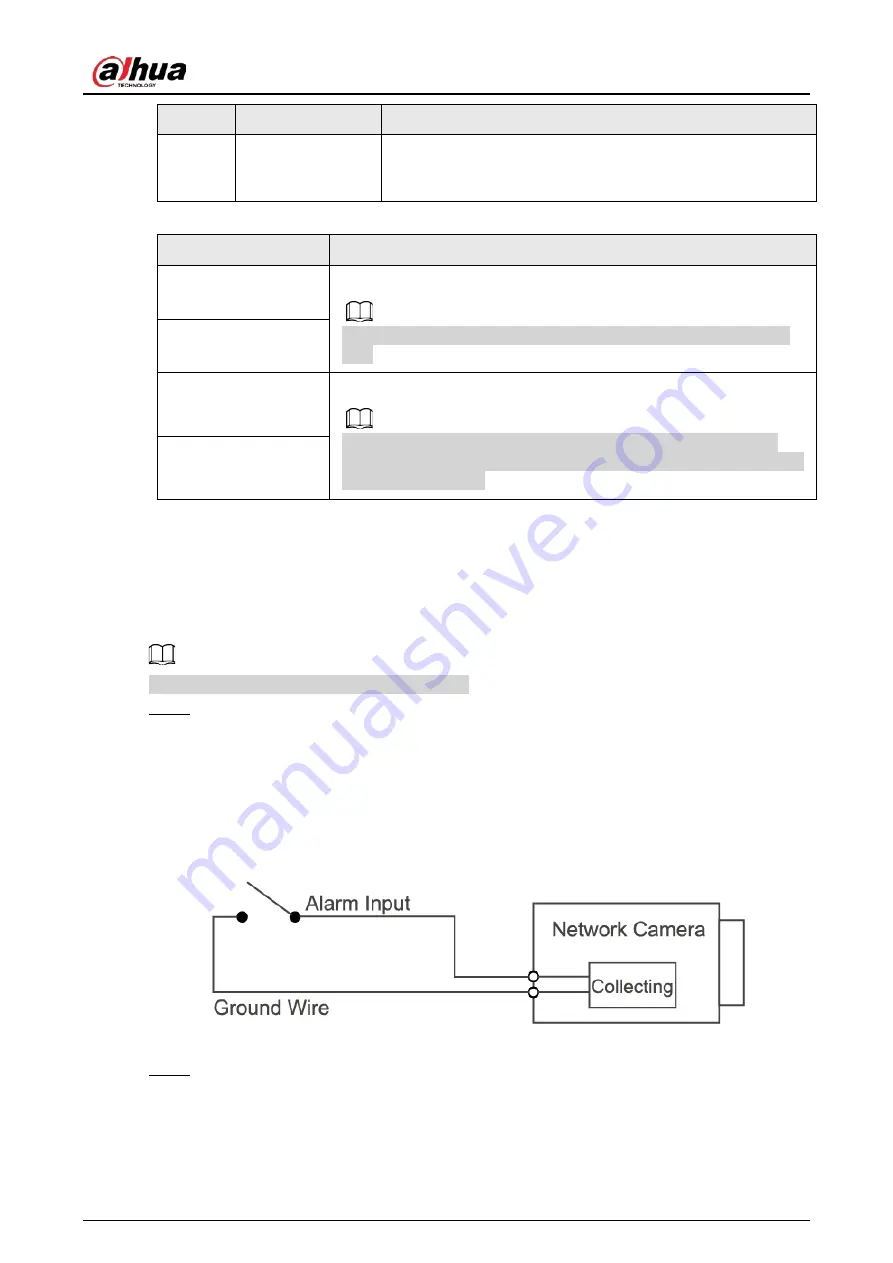
Connect the alarm input device to the alarm input end of the I/O port. See Figure 1-2.
The device collects different statuses of the alarm input port while the input signal is idling
and being grounded.
●
Device collects logic "1" when the input signal is connected to +3 V to +5 V or idling.
●
Device collects logic "0" when the input signal is grounded.
Figure 1-2 Alarm input
Step 2
Connect the alarm output device to the alarm output end of the I/O port. The alarm output
is an open-drain output, which works in the following modes.
●
Mode A: level application. The alarm outputs high and low level signals, and the alarm
outlet is OD, which requires external pull-up resistance (10K Ohm typical) to work. The
maximum external pull-up level is 12 V, maximum port current is 300 mA, and the


