S0707260
Page 3
Swing Motor
GENERAL DESCRIPTION
THEORY OF OPERATION
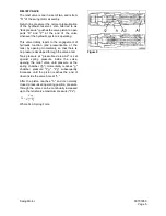
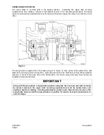
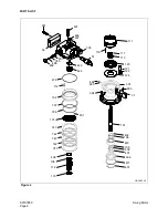
The cross sectional views of the swing motor, show most of the main components of an axial-piston type
hydraulic motor. Arrows indicating direction of flow and other graphic symbols provide a general guide for
understanding basic operation (Figure 1).
When high-pressure oil enters the cylinder through the inlet port of the valve plate (1, Figure 1), the sliding
piston inside the cylinder is driven back, generating force "F" against the shoe behind the piston (2).
Force "F" acts in two different directions, as indicated by the arrows (Figure 1). Force F1 exerts pressure
directly on the swash plate (3) to generate oil flow through the motor, while force F2 pushes laterally - at a
right angle - against the drive shaft, providing the rotational energy to turn the cylinder block around the
drive shaft.
All nine pistons in the cylinder block have equal width bore, length and volume. They are configured in a
concentric layout around the drive shaft, as shown in the cross section end-view. As oil is forced through
the inlet port, pistons rotating past the pressurized (supply) side of the motor (indicated as the shaded
cylinders) transmit drive torque - one after the next, each in turn - to the swash plate (through F1, direct
output force) and to the cylinder block (F2, lateral force to keep the block rotating).
Figure 1
Reference
Number
Description
1
Valve Plate
2.
Shoe
3.
Swash Plate
4.
Cylinder Block
5.
Piston
Reference
Number
Description
Содержание Solar 470LC-V
Страница 2: ......
Страница 4: ......
Страница 7: ...1SAFETY...
Страница 8: ......
Страница 46: ...S0102000 Page 38 Track Excavator Safety...
Страница 47: ...1SPECIFICATIONS...
Страница 48: ......
Страница 54: ...S0202090K Page 6 Specifications for Solar 470LC V...
Страница 70: ...S0202090K Page 22 Specifications for Solar 470LC V...
Страница 71: ...1GENERAL MAINTENANCE...
Страница 72: ......
Страница 86: ...S0302000 Page 14 General Maintenance Procedures Return to Master Table of Contents...
Страница 99: ...1UPPER STRUCTURE...
Страница 100: ......
Страница 102: ...S0402040K Page 2 Cab TABLE OF CONTENTS Removal 3 Installation 6...
Страница 110: ...S0403050K Page 2 Counterweight Return to Master Table of Contents TABLE OF CONTENTS General 3 Removal 5 Installation 7...
Страница 116: ...S0403050K Page 8 Counterweight Return to Master Table of Contents...
Страница 120: ...S0405120K Page 4 Fuel Tank PARTS LIST 3 7 5 6 4 23 10 9 8 19 14 35 35 33 33 20 12 11 13 26 16 1 FRONT ASS1180L Figure 1...
Страница 140: ...S0407000 Page 6 Swing Bearing...
Страница 155: ...S0408060 Page 15 Swing Reduction Gearbox...
Страница 163: ...1LOWER STRUCTURE AND CHASSIS...
Страница 164: ......
Страница 188: ...S0505120 Page 24 Track Assembly Return to Master Table of Contents 7 Tighten plug 1 Figure 49 Figure 49...
Страница 190: ...S0505120 Page 26 Track Assembly Return to Master Table of Contents...
Страница 191: ...1ENGINE AND DRIVE TRAIN...
Страница 192: ......
Страница 203: ...S0605060K Page 11 Air Conditioner Face and Defroster ARS1300L Figure 12...
Страница 218: ...S0605060K Page 26 Air Conditioner...
Страница 227: ...1HYDRAULICS...
Страница 228: ......
Страница 258: ...S0702190K Page 30 Hydraulic System Troubleshooting Testing and Adjustment...
Страница 260: ...S0703010K Page 2 Accumulator TABLE OF CONTENTS General Description 3 Specifications 4...
Страница 264: ...S0703010K Page 6 Accumulator...
Страница 272: ...S0704090K Page 8 Center Joint Swivel...
Страница 281: ...S0705000 Page 9 Cylinders...
Страница 284: ...S0705000 Page 12 Cylinders P S Power Steering O R Out Rigger MODEL CYLINDER A 0 1 B C D MODEL CYLINDER...
Страница 285: ...S0705000 Page 13 Cylinders...
Страница 289: ...S0705000 Page 17 Cylinders...
Страница 294: ...S0705000 Page 22 Cylinders SLIPPER SEAL JIG ARS4770L A 2 A A 14 B B 40 5 R 1 0 R1 1 0 Figure 10...
Страница 297: ...S0705000 Page 25 Cylinders...
Страница 298: ...S0705000 Page 26 Cylinders SLIPPER SEAL STRAIGHTENING JIG ARS4780L 2 R1 50 25 100 A 15 A 2 5 R 2 C 1 Figure 11...
Страница 306: ...S0705000 Page 34 Cylinders 17 Force out pin bushing 1 from body of cylinder Figure 28...
Страница 310: ...S0705000 Page 38 Cylinders...
Страница 317: ...S0707260 Page 7 Swing Motor...
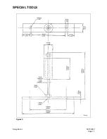
Страница 321: ...S0707260 Page 11 Swing Motor SPECIAL TOOLS Figure 5...
Страница 338: ...S0707260 Page 28 Swing Motor...
Страница 350: ...S0707365 Page 12 Travel Motor With Gearbox A6V160HD PARTS LIST Travel Motor Figure 12 HTS6331...
Страница 352: ...S0707365 Page 14 Travel Motor With Gearbox A6V160HD Travel Motor Rotary Group Figure 13 HTS6321...
Страница 354: ...S0707365 Page 16 Travel Motor With Gearbox A6V160HD Travel Motor Control HTS6331 Figure 14...
Страница 356: ...S0707365 Page 18 Travel Motor With Gearbox A6V160HD Travel Motor Speed Reduction Gearbox Assembly 3033 Figure 15...
Страница 361: ...S0707365 Page 23 Travel Motor With Gearbox A6V160HD TRAVEL MOTOR DISASSEMBLY SECTIONAL VIEW HTS063S Figure 16...
Страница 383: ...S0707365 Page 45 Travel Motor With Gearbox A6V160HD 29 Remove gasket Figure 91 Figure 91 3061...
Страница 401: ...S0708325K Page 3 Main Pump Rexroth...
Страница 402: ...S0708325K Page 4 Main Pump Rexroth SECTIONAL VIEW A8VO200LA1KH1 63 ASS0010L Figure 1...
Страница 403: ...S0708325K Page 5 Main Pump Rexroth ASS0020L Figure 2...
Страница 413: ...S0708325K Page 15 Main Pump Rexroth 2 Sealing surface of housing 2 Figure 27 2 ASS0270L Figure 28...
Страница 414: ...S0708325K Page 16 Main Pump Rexroth REMOVE THE CONTROL HOUSING ASS0280L Figure 29...
Страница 439: ...S0708325K Page 41 Main Pump Rexroth 4 Gear tooth marks must align with each other ASS0860L Figure 87...
Страница 447: ...S0708325K Page 49 Main Pump Rexroth 5 Install seal and controller ASS1040L Figure 105 ASS1050L Figure 106...
Страница 450: ...S0708325K Page 52 Main Pump Rexroth INSTALLATION OF COVER AUXILIARY DRIVE ASS1100L Figure 111...
Страница 454: ...S0708325K Page 56 Main Pump Rexroth...
Страница 459: ...S0709402K Page 5 Control Valve Kayaba Model KVMG 400 DA...
Страница 461: ...S0709402K Page 7 Control Valve Kayaba Model KVMG 400 DA Figure 1...
Страница 463: ...S0709402K Page 9 Control Valve Kayaba Model KVMG 400 DA Figure 2...
Страница 465: ...S0709402K Page 11 Control Valve Kayaba Model KVMG 400 DA Figure 3...
Страница 475: ...S0709402K Page 21 Control Valve Kayaba Model KVMG 400 DA...
Страница 477: ...S0709402K Page 23 Control Valve Kayaba Model KVMG 400 DA Figure 13...
Страница 483: ...S0709402K Page 29 Control Valve Kayaba Model KVMG 400 DA PARTS LIST Figure 30...
Страница 484: ...S0709402K Page 30 Control Valve Kayaba Model KVMG 400 DA Figure 31...
Страница 485: ...S0709402K Page 31 Control Valve Kayaba Model KVMG 400 DA Figure 32...
Страница 509: ...S0709402K Page 55 Control Valve Kayaba Model KVMG 400 DA Figure 57 S N 1051 and Up...
Страница 512: ...S0709402K Page 58 Control Valve Kayaba Model KVMG 400 DA...
Страница 558: ...S0792170K Page 2 Hydraulic Schematic S470LC V TABLE OF CONTENTS General Description 3 Solar 470LC V 4...
Страница 560: ...S0792170K Page 4 Hydraulic Schematic S470LC V SOLAR 470LC V Figure 2...
Страница 561: ...S0792170K Page 5 Hydraulic Schematic S470LC V...
Страница 562: ...S0792170K Page 6 Hydraulic Schematic S470LC V...
Страница 563: ...1ELECTRICAL SYSTEM...
Страница 564: ......
Страница 618: ...S0802220K Page 54 Electrical System...
Страница 637: ...S0802220K Page 73 Electrical System...
Страница 642: ...S0892170K Page 2 Electrical Schematic S470LC V TABLE OF CONTENTS General Description 3 Solar 470LC V 4...
Страница 644: ...S0892170K Page 4 Electrical Schematic S470LC V SOLAR 470LC V Figure 2...
Страница 646: ...S0892170K Page 6 Electrical Schematic S470LC V...
Страница 647: ...1ATTACHMENTS...
Страница 648: ......
Страница 663: ...S0904005K Page 7 Bucket 5 Roll the new O ring 1 Figure 9 into the O ring groove ARO1392L 1 Figure 9...
Страница 668: ......


