S0702190K
Page 22
Hydraulic System Troubleshooting, Testing and
Adjustment
SWING SYSTEM TROUBLESHOOTING
PRECAUTIONS/INITIAL CHECKS
1.
Stop work. Release all weight or any type of load safely before proceeding. Avoid risking injury or
adding to damage.
2.
Turn off engine and disengage control functions until initial tests are ready to be made.
Stop the machine, put the boom and arm in the inoperative (overnight park) position and begin by making
the fastest, simplest checks first:
•
Check oil level.
•
Check for overheating, oil leaks, external oil cooler clogging or broken fan belt. Consult service
record for prior repair/service work.
•
Drain some tank oil to a clean, clear container. Look for metal shavings/grit, cloudiness/water or
foam/air bubbles in the oil.
•
Check for wobble through the engine/pump flex coupling. Run engine with the pump input
hydraulic power control nut turned to the lowest power to check the engine.
•
Investigate unusual operating noises or vibration. Check for loose bolts, connections.
SWING RELIEF VALVE CHECKING AND ADJUSTMENT
Make a check of operating pressures through the swing relief valve if:
•
The swing motor fails to turn.
•
Swings in one direction only.
•
Swings but continues to coast.
•
There is drifting on a slope.
1.
Check operation by connecting:
A.
Two 600 bar (8,700 psi) pressure gauges to the inlet and outlet measuring ports on top of the
swing motor.
Pressure should be between 270 - 280 bar (3,916 - 4,061 psi), with both swing locks engaged.
With swing locks released, during full acceleration and deceleration, pressure should approach
250 bar (3,625 psi) in each direction.
B.
Connect a 60 bar (870 psi) pressure gauge at the "SH" port of the hydraulic brake.
Pressure should always stay at or above 4 bar (58 psi) when operating swing, boom or arm.
WARNING
Prevent possible injury and/or loss of operating control. Stop work and park the excavator at the
first indication of:
1.
Equipment breakdown
2.
Inadequate control response
3.
Erratic performance
Содержание Solar 470LC-V
Страница 2: ......
Страница 4: ......
Страница 7: ...1SAFETY...
Страница 8: ......
Страница 46: ...S0102000 Page 38 Track Excavator Safety...
Страница 47: ...1SPECIFICATIONS...
Страница 48: ......
Страница 54: ...S0202090K Page 6 Specifications for Solar 470LC V...
Страница 70: ...S0202090K Page 22 Specifications for Solar 470LC V...
Страница 71: ...1GENERAL MAINTENANCE...
Страница 72: ......
Страница 86: ...S0302000 Page 14 General Maintenance Procedures Return to Master Table of Contents...
Страница 99: ...1UPPER STRUCTURE...
Страница 100: ......
Страница 102: ...S0402040K Page 2 Cab TABLE OF CONTENTS Removal 3 Installation 6...
Страница 110: ...S0403050K Page 2 Counterweight Return to Master Table of Contents TABLE OF CONTENTS General 3 Removal 5 Installation 7...
Страница 116: ...S0403050K Page 8 Counterweight Return to Master Table of Contents...
Страница 120: ...S0405120K Page 4 Fuel Tank PARTS LIST 3 7 5 6 4 23 10 9 8 19 14 35 35 33 33 20 12 11 13 26 16 1 FRONT ASS1180L Figure 1...
Страница 140: ...S0407000 Page 6 Swing Bearing...
Страница 155: ...S0408060 Page 15 Swing Reduction Gearbox...
Страница 163: ...1LOWER STRUCTURE AND CHASSIS...
Страница 164: ......
Страница 188: ...S0505120 Page 24 Track Assembly Return to Master Table of Contents 7 Tighten plug 1 Figure 49 Figure 49...
Страница 190: ...S0505120 Page 26 Track Assembly Return to Master Table of Contents...
Страница 191: ...1ENGINE AND DRIVE TRAIN...
Страница 192: ......
Страница 203: ...S0605060K Page 11 Air Conditioner Face and Defroster ARS1300L Figure 12...
Страница 218: ...S0605060K Page 26 Air Conditioner...
Страница 227: ...1HYDRAULICS...
Страница 228: ......
Страница 258: ...S0702190K Page 30 Hydraulic System Troubleshooting Testing and Adjustment...
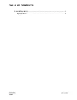
Страница 260: ...S0703010K Page 2 Accumulator TABLE OF CONTENTS General Description 3 Specifications 4...
Страница 264: ...S0703010K Page 6 Accumulator...
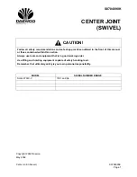
Страница 272: ...S0704090K Page 8 Center Joint Swivel...
Страница 281: ...S0705000 Page 9 Cylinders...
Страница 284: ...S0705000 Page 12 Cylinders P S Power Steering O R Out Rigger MODEL CYLINDER A 0 1 B C D MODEL CYLINDER...
Страница 285: ...S0705000 Page 13 Cylinders...
Страница 289: ...S0705000 Page 17 Cylinders...
Страница 294: ...S0705000 Page 22 Cylinders SLIPPER SEAL JIG ARS4770L A 2 A A 14 B B 40 5 R 1 0 R1 1 0 Figure 10...
Страница 297: ...S0705000 Page 25 Cylinders...
Страница 298: ...S0705000 Page 26 Cylinders SLIPPER SEAL STRAIGHTENING JIG ARS4780L 2 R1 50 25 100 A 15 A 2 5 R 2 C 1 Figure 11...
Страница 306: ...S0705000 Page 34 Cylinders 17 Force out pin bushing 1 from body of cylinder Figure 28...
Страница 310: ...S0705000 Page 38 Cylinders...
Страница 317: ...S0707260 Page 7 Swing Motor...
Страница 321: ...S0707260 Page 11 Swing Motor SPECIAL TOOLS Figure 5...
Страница 338: ...S0707260 Page 28 Swing Motor...
Страница 350: ...S0707365 Page 12 Travel Motor With Gearbox A6V160HD PARTS LIST Travel Motor Figure 12 HTS6331...
Страница 352: ...S0707365 Page 14 Travel Motor With Gearbox A6V160HD Travel Motor Rotary Group Figure 13 HTS6321...
Страница 354: ...S0707365 Page 16 Travel Motor With Gearbox A6V160HD Travel Motor Control HTS6331 Figure 14...
Страница 356: ...S0707365 Page 18 Travel Motor With Gearbox A6V160HD Travel Motor Speed Reduction Gearbox Assembly 3033 Figure 15...
Страница 361: ...S0707365 Page 23 Travel Motor With Gearbox A6V160HD TRAVEL MOTOR DISASSEMBLY SECTIONAL VIEW HTS063S Figure 16...
Страница 383: ...S0707365 Page 45 Travel Motor With Gearbox A6V160HD 29 Remove gasket Figure 91 Figure 91 3061...
Страница 401: ...S0708325K Page 3 Main Pump Rexroth...
Страница 402: ...S0708325K Page 4 Main Pump Rexroth SECTIONAL VIEW A8VO200LA1KH1 63 ASS0010L Figure 1...
Страница 403: ...S0708325K Page 5 Main Pump Rexroth ASS0020L Figure 2...
Страница 413: ...S0708325K Page 15 Main Pump Rexroth 2 Sealing surface of housing 2 Figure 27 2 ASS0270L Figure 28...
Страница 414: ...S0708325K Page 16 Main Pump Rexroth REMOVE THE CONTROL HOUSING ASS0280L Figure 29...
Страница 439: ...S0708325K Page 41 Main Pump Rexroth 4 Gear tooth marks must align with each other ASS0860L Figure 87...
Страница 447: ...S0708325K Page 49 Main Pump Rexroth 5 Install seal and controller ASS1040L Figure 105 ASS1050L Figure 106...
Страница 450: ...S0708325K Page 52 Main Pump Rexroth INSTALLATION OF COVER AUXILIARY DRIVE ASS1100L Figure 111...
Страница 454: ...S0708325K Page 56 Main Pump Rexroth...
Страница 459: ...S0709402K Page 5 Control Valve Kayaba Model KVMG 400 DA...
Страница 461: ...S0709402K Page 7 Control Valve Kayaba Model KVMG 400 DA Figure 1...
Страница 463: ...S0709402K Page 9 Control Valve Kayaba Model KVMG 400 DA Figure 2...
Страница 465: ...S0709402K Page 11 Control Valve Kayaba Model KVMG 400 DA Figure 3...
Страница 475: ...S0709402K Page 21 Control Valve Kayaba Model KVMG 400 DA...
Страница 477: ...S0709402K Page 23 Control Valve Kayaba Model KVMG 400 DA Figure 13...
Страница 483: ...S0709402K Page 29 Control Valve Kayaba Model KVMG 400 DA PARTS LIST Figure 30...
Страница 484: ...S0709402K Page 30 Control Valve Kayaba Model KVMG 400 DA Figure 31...
Страница 485: ...S0709402K Page 31 Control Valve Kayaba Model KVMG 400 DA Figure 32...
Страница 509: ...S0709402K Page 55 Control Valve Kayaba Model KVMG 400 DA Figure 57 S N 1051 and Up...
Страница 512: ...S0709402K Page 58 Control Valve Kayaba Model KVMG 400 DA...
Страница 558: ...S0792170K Page 2 Hydraulic Schematic S470LC V TABLE OF CONTENTS General Description 3 Solar 470LC V 4...
Страница 560: ...S0792170K Page 4 Hydraulic Schematic S470LC V SOLAR 470LC V Figure 2...
Страница 561: ...S0792170K Page 5 Hydraulic Schematic S470LC V...
Страница 562: ...S0792170K Page 6 Hydraulic Schematic S470LC V...
Страница 563: ...1ELECTRICAL SYSTEM...
Страница 564: ......
Страница 618: ...S0802220K Page 54 Electrical System...
Страница 637: ...S0802220K Page 73 Electrical System...
Страница 642: ...S0892170K Page 2 Electrical Schematic S470LC V TABLE OF CONTENTS General Description 3 Solar 470LC V 4...
Страница 644: ...S0892170K Page 4 Electrical Schematic S470LC V SOLAR 470LC V Figure 2...
Страница 646: ...S0892170K Page 6 Electrical Schematic S470LC V...
Страница 647: ...1ATTACHMENTS...
Страница 648: ......
Страница 663: ...S0904005K Page 7 Bucket 5 Roll the new O ring 1 Figure 9 into the O ring groove ARO1392L 1 Figure 9...
Страница 668: ......


