5. DIRECTIONS FOR DISASSEMBLY AND ADJUSTMENT
11
DIRECTIONS
Gear Mechanism Ass’y Replacement
BEFORE ATTEMPTING TO SERVICE OR ADJUST ANY PART OF THE WASHING MACHINE, DISCONNECT
THE POWER CORD FROM THE ELECTRIC OUTLET.
Warning
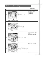
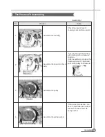
GEAR MECHANISM ASS’Y REPLACEMENT
1
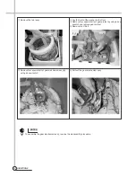
Raise the top plate on the outer cabinet.
2
Loosen four screws mounting outer tub cover and
remove outer tub cover from the tub ass’y.
4
Loosen the pulsator mounting screw and remove the
pulsator.
3
Remove the cap pulsator from the pulsator assy by
using screw driver
5
Remove the special nut by using “T” type box wrentch.
6
Remove the special washer.
Содержание DWF-H361ASA
Страница 27: ...APPENDIX 26 PCB ASS Y Wiring Diagram...
Страница 29: ...28 PARTS DIAGRAM...
Страница 30: ...29 PARTS DIAGRAM C01 C04 C02 C03 C05 C06 C08 C07 C10 C11 C12 C12 C09 C13 C14 C15 C16 C17 C18...
Страница 31: ...30 PARTS DIAGRAM D01 D02 D03 D04 D05 D06 D07 D08 D09 D10 D11 D12 D13 D14 D15 D16 D17 D18...


