


14
CIRCUIT
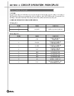
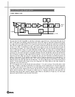
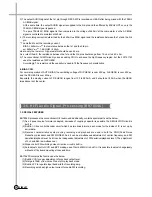
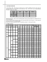
4. TM BLOCK
The TUNER and MODULATOR which is separated to each module conventionally, is presently united to one block
(TM block)
(a) PLL METHOD AND I
2
C-BUS CONTROL
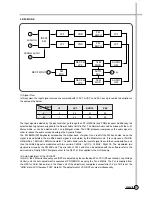
The RF OUTPUT channel can be varied from 22CH to 69CH by remote control using PLL method and I
2
C-BUS
control.
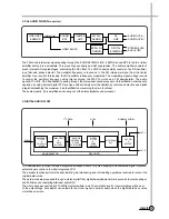
Moreover, SYSTEM(PAL, MESECAM), SOUND CARRIER FREQUENCY, AND TPSG(TEST PATTERN SIGNAL
GENERATOR) can be changed by remote control as well.
The P/S ratio, white clip, power saving, etc., also can be controlled only by changing a I
2
C-BUS data according to
the designer’s intention.
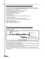
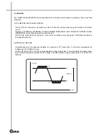
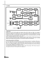
(b) DIGITAL AFT METHOD
Conventionally, when the frequency deviates, the variation of AFT output from IF circuit was compensated by
feedbacking it to TUNER AFT input.
On the other hand, if AFT, which is currently adopted to these models from IF circuit deviates the window range,
the VT value is changed to maintain the AFT voltage to be within window range by checking AFT(+) and AFT(-) on
MICOM.
VOLTAGE
AFT(+)
3V
WINDOW
2V
FREQ.
AFT(-)
Содержание DV-K88 series
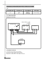
Страница 71: ...68 CIRCUIT DIAGRAMS 9 1 Connection Diagram SECTION 9 CIRCUIT DIAGRAM 68...
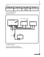
Страница 72: ...69 CIRCUIT DIAGRAMS R819 5 1 9 2 Power Circuit Diagram...
Страница 73: ...70 CIRCUIT DIAGRAMS 9 3 Syscon and Logic Circuit Diagram...
Страница 74: ...71 CIRCUIT DIAGRAMS 9 4 AV SW Circuit Diagram...
Страница 75: ...72 CIRCUIT DIAGRAMS 9 5 IF PDC Circuit Diagram TM...
Страница 76: ...73 CIRCUIT DIAGRAMS 9 6 If Module Circuit Diagram A2...
Страница 77: ...74 CIRCUIT DIAGRAMS 9 7 If Module Circuit Diagram Nicam...
Страница 78: ...75 CIRCUIT DIAGRAMS 9 8 Hi Fi Pre Amp Circuit Diagram...
Страница 79: ...76 CIRCUIT DIAGRAMS 9 9 Video Audio Circuit Diagram...
Страница 80: ...77 CIRCUIT DIAGRAMS 9 10 Remocon Circuit Diagram...
Страница 81: ...SECTION 10 COMPONENTS LOCATION GUIDE ON PCB BOTTOM VIEW 78 P C B LOCATION 10 1 PCB Main...
Страница 82: ...80 P C B LOCATION 10 3 PCB Logic DV K8K S S Series DV K86 S S Series DV K82 S S Series...
Страница 83: ...81 P C B LOCATION DV K88 S S Series...
Страница 84: ...SECTION 11 DISASSEMBLY 83 DISASSEMBLY 11 1 Packing Ass y...
Страница 85: ...84 DIAGRAMS DV K88 Series DV K82 Series DV K8K Series DV K86 Series 11 2 Front Panel Assembly...