55
2) Audio circuit
1) Outline
This Audio Circuit use LA71004M A/V one chip IC of Sanyo's. The major feature of this IC is that has a Recording Bias current auto-
control circuit. So it is controlled by circuit automatically to keep consistent Recording current regardless change of head impedance.
Prior IC is used variable resistor to control Recording current passively.
But, variation range of HEAD Impedance has to be limited because of this auto-control circuit.
• R/P HEAD = 58 KOHM ± 15% (f = 70KHz)
• A/E HEAD = 34 OHM ± 20% (f = 70KHz)
¢¡
Serial Type
= 180 OHM ± 20% (f = 70KHz)
¢¡
Parallel Type
• FE HEAD = 80 OHM ± 15% (f = 70KHz)
It can be devided a parallel and a serial circuit by form of connection of AE Head & FE Head. In case of D/W, we adopt a serial-type
circuit.
2) Name and operation of pins in audio IC
!
Features
i) 1 chip type including PB amp, Line Amp, REC amp, ALC circuit, EQ switch Auto REC bias circuit.
ii) It is equipped with EQ switch which operates in SP/LP/EP modes respectively.
iii) ALC level is fixed on-6dBv.
@
Function
Pin No
Name
Function
1
Auto-Bias-IN
320±10mVrms Input for auto-bias
2
EQ-SW2
Capacitor switch for head resonance in LP or EP SW ON
3
Auto-Bias-OUT
DC control voltage for auto-bias
4
Auto-Bias
Auto-Bias
5
EQ-IN
Line input, Input impedance: 120k
Ω
6
EQ-NFB
Negative Feedback of PB Amp
7
EQ-SW1
Playback equalizer switch in SP mode SW ON
8
EQ-OUT
Playback Amp out
9
Line-BP-IN
Line Amp input of playback Amp out
54
Mute ON/OFF
Mute control
55
PB/EE
PB/EE mode control
56
Audio REC/EE/PB
REC/EE control
57
Line IN
Line/Tuner input
58
ALC-DET
Port for ALC filter (setup attact or recovery time)
59
Line OUT
Line Amp out
60
REC IN
Input to REC Amp
61
Vcc
Vcc
62
Vref Filter
Vref filter (Ripple filter)
63
GND
GND
64
REC-OUT
Recording Amp out
Содержание DV- K504N-SJ
Страница 35: ...34 AC001 K584NZ SJ M K584NZ SG M only...
Страница 36: ...35...
Страница 37: ...36...
Страница 38: ...37...
Страница 39: ...38...
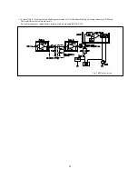
Страница 60: ...59 ELECTRICAL ADJUSTMENTS Fig 1 Circuit Board Location...
Страница 92: ...91 INTERCONNECT WIRING DIAGRAM K584N K484N K384N K284N...
Страница 93: ...92 POWER SUPPLY SCHEMATIC DIAGRAM FREE VOLTAGE K584NY SJ M K584NZ SJ M K584NZ SG M...
Страница 95: ...94 2HD HEAD AMP SCHEMATIC DIAGRAM K384N K284N K304N...
Страница 96: ...95 4HD HEAD AMP SCHEMATIC DIAGRAM K584N K484N K504N...
Страница 97: ...96 VIDEO AUDIO SCHEMATIC DIAGRAM K584N K484N K384N K284N K504N K304N...
Страница 98: ...97 PIF INPUT SELECTOR SCHEMATIC DIAGRAM 9V USE K584NY SJ M K584NZ SJ M K584NZ SG M...
Страница 100: ...99 TIMER SYSCON SCHEMATIC DIAGRAM K584N K484N K384N K284N K504N K304N...
Страница 101: ...100 POWER SUPPLY BLOCK DIAGRAM FREE VOLTAGE K584NY SJ M K584NZ SJ M K584NZ SG M...
Страница 103: ...102 2HD HEAD AMP BLOCK DIAGRAM K384N K284N K304N...
Страница 104: ...103 4HD HEAD AMP BLOCK DIAGRAM K584N K484N K504N...
Страница 105: ...104 VIDEO AUDIO BLOCK DIAGRAM K584N K484N K384N K284N K504N K304N...
Страница 106: ...105 PIF INPUT SELECTOR BLOCK DIAGRAM K584N K484N K384N K284N K504N K304N...
Страница 107: ...106 SYSCON SERVO BLOCK DIAGRAM K584N K484N K384N K284N K504N K304N SEG A SEG L SEG A SEG L SEG C SEG F G1 G8 G1 G8...
Страница 109: ...108 MAIN PCB 2HEAD 4HEAD...


