


ENGLISH
92
4.2.3
Connection and setting of the optical coupling inputs
The inputs of the inverter are photocoupled (see para. 2.2.4 and 6.6.13); this means that galvanic separation of the inputs from the
inverter is guaranteed, to enable the functions for the float, auxiliary pressure, system disable, and low pressure on intake. The
functions are indicated respectively by the messages F1, Paux, F3, F4. If activated, the Paux function boosts the pressure in the
system to the set pressure, see par. 6.6.13.3. The functions F1, F3, F4 stop the pump for 3 different reasons, see par. 6.6.13.2,
6.6.13.4, 6.6.13.5.
When using a multiple inverter system, the inputs must be used with the following settings:
•
the contacts that perform the auxiliary pressures must be connected in parallel on all the inverters so that the same signal
arrives on all the inverters.
•
the contacts that perform the functions F1, F3, F4 may be connected either with independent contacts for each inverter, or
with only one contact connected in parallel on all the inverters (the function is activated only on the inverter at which the
command arrives).
The parameters for setting the inputs I1, I2, I3, I4 are part of the sensitive parameters, so setting one of these on any inverter means
that they are automatically aligned on all the inverters. As the setting of the inputs not only selects the function, but also the type of
polarity of the contact, the function associated with the same type of contact will perforce be found on all the inverters. For the above
reason, when using independent contacts for each inverter (as is possible for the functions F1, F3, F4), these must all have the same
logic for the various inputs with the same name; that is, for the same input, either normally open contacts are used for all the inverters
or normally closed ones.
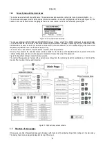
4.3
Multi inverter operating parameters
The parameters displayed on the menu, in a multi-inverter configuration, can be classed as follows:
•
Read-only parameters
•
Local parameters
•
Multi inverter system configuration parameters
in turn divided as
o
Sensitive parameters
o
Parameters with optional alignment
4.3.1
Parameters related to multi inverter systems
4.3.1.1
Local parameters
These are parameters that can differ from one inverter to another and in some cases actually need to be different. For these
parameters, automatic alignment of inverter configuration is not admitted. In the case of manual assignment of addresses, these must
all be different.
List of local parameters for inverters:
CT
Contrast
FP
Test frequency in manual mode
RT
Direction of rotation
AD
Address
IC
Reserve configuration
RF
Fault and warning reset
4.3.1.2
Sensitive parameters
These are parameters that must be aligned on the entire series for control purposes.
List of sensitive parameters:
SP
Setpoint pressure
P1
Input 1 auxiliary pressure
P2
Input 2 auxiliary pressure
P3
Input 3 auxiliary pressure
P4
Input 4 auxiliary pressure
FN Nominal frequency
RP
Pressure drop for restart
Содержание MCE-150/P
Страница 308: ...306 IEC 60634 1...
Страница 309: ...307 1 6 1 1...
Страница 312: ...310 1 2 1 1 1 1 2 5 2 1 2 1 2...
Страница 313: ...311 2 1 1 2 1 2 L L L 2 2 4 2 15 2 2 1 1a...
Страница 314: ...312 2a 3a 4b 1b 127 240 240 480...
Страница 318: ...316 GP GI 6 6 4 6 6 5 7 A B C D...
Страница 320: ...318 9 4 20 7 4 20 PR 6 5 7 4 20 2 18 J5 GND 1 J5 GND o IN 11 J5 o OUT 7 J5 4 20 7 OUT 8 10 11 IN...
Страница 323: ...321 50 60 7 DC AC 50 60 8 6 2 1 5 36 36 12 3 3 3 3 2 13 9 10 8...
Страница 324: ...322 12 J5 I1 11 17 16 18 16 17 I2 11 15 16 18 15 16 I3 11 14 13 18 13 14 I4 11 12 13 8 12 13 10 10 I1 1 I2 3 I3 5 I4 10...
Страница 325: ...323 I1 F1 I1 6 6 13 2 I2 P2 6 6 13 3 I3 F3 6 6 13 4 I4 1 F4 6 6 13 5 10 GND 7 I1 I2 I3 I4...
Страница 326: ...324 3 13 64 X 128 4 MODE SET 11 SET 9 MODE 1 SET 11 3 EEprom SET 6 SET MODE 3 1 11...
Страница 327: ...325 3 2 1 2 3 2 1 MODE SET MODE 10 2 2 5 5 5 2 2 12...
Страница 329: ...327 12 SET 14 15 13 15 3 3...
Страница 330: ...328 12 14 16 GO SB BL LP HP EC OC OF SC OT OB BP NC F1 F3 F4 P1 1 P2 2 P3 3 P4 4 E0 E16 0 16 EE EEprom WARN...
Страница 331: ...329 15 14 3 4 PW 6 6 16 GO SB...
Страница 332: ...330 4 4 1 Link 8 4 2 4 2 1 Link Link 15...
Страница 333: ...331 17 Link 4 2 2 0 5V 4 20 A 0 4 2 2 1 FI FI 4 2 2 2 FZ 6 5 9 1 4 2 2 3 0 5 4 20 A 0 5 0...
Страница 336: ...334 4 4 2 2 4 2 5 4 5 ET 6 6 9 FL 4 5 1 4 5 1 1 ET ET ET ET 0 ET 6 6 9 4 5 1 2 23 23...
Страница 339: ...337 FZ FZ 2 35 FZ 37 FZ FZ FZ FZ FI 0 FZ FZ 0 5 1 7 6 GI GP FL TB...
Страница 341: ...339 6 6 1 MODE MODE 6 1 1 FR 6 1 2 VP 6 1 3 C1 A C1 RC 6 5 1 6 1 4 PO PO 6 1 5 SM 15 SB F 17 SM 15 F Sb RC A...
Страница 342: ...340 SM 6 1 6 VE 26 1 0 S 5 6 2 2 SET MODE 6 2 1 VF 6 2 2 TE 6 2 3 BT 6 2 4 FF FF x y x y x 1 x y 64 RF 6 2 5 CT 6 2 6 LA...
Страница 362: ...360 OC 10 6 OF 10 6 33 8 8 1 PMW 4 2 8 2 8 3 8 3 SET EE EEprom FLASH...
Страница 548: ...546 IEC 364 1 inverter...
Страница 549: ...547 1 Inverter inverter inverter 6 inverter 1 1...
Страница 552: ...550 1 2 1 1 inverter inverter 1 1 2 5 inverter inverter 2 1 inverter inverter 2 1 2 C...
Страница 554: ...552 2a 3a 4b...
Страница 558: ...556 GP GI 6 6 4 6 6 5 inverter 7 A B C D...
Страница 563: ...561 I 2 15 16 I 3 13 14 I 4 12 13 50 60 Hz 7 DC V AC 50 60 Hz Vrms V 8 6 V 2 1 5 V 36 36 12V mA 3 3 3 3 mm 2 13 9 10 8...
Страница 564: ...562 11 J5 pin Pin I1 11 17 16 18 16 17 I2 11 15 16 18 15 16 I3 11 14 13 18 13 14 I4 11 12 13 8 12 13 10...
Страница 565: ...563 10 I1 1 I2 3 I3 5 I4 10 I1 F1 I1 6 6 13 2 I2 P2 6 6 13 3 I3 F3 6 6 13 4 I4 1 F4 6 6 13 5 10 V GND 7 1 2 3 4...
Страница 566: ...564 3 12 oled 64 X 128 4 MODE SET 11 SET inverter 9 MODE 1 SET 11 3 EEprom SET 6 SET MODE 3 1 11...
Страница 567: ...565 3 2 1 2 3 2 1 MODE SET Setpoint MODE 10 ONOMA TOY MENOY 2 Setpoint 2 5 5 5 2 2 12...
Страница 569: ...567 3 2 2 12 SET 13 MAIN UTENTE MONITOR MENU ESTESO MENU ESTESO PASSWORD PASSWORD Setpoint 15 13 14...
Страница 571: ...569 15 15 14 3 4 Password inverter password password inverter password PW 6 6 16 GO SB FAULT...
Страница 728: ...726 IEC 364 1 1...
Страница 729: ...727 1 1...
Страница 732: ...730 1 2 1 1 1 2 5 2 1 2 1 2 C...
Страница 733: ...731 2 1 1 0 2 1 2 L L L 2 2 4 2 15 2 2 1 1...
Страница 734: ...732 2a 3a 4b...
Страница 738: ...736 GP GI 6 6 4 6 6 5 7 2 2 3 2 Press Flow 6 A B C D...
Страница 743: ...741 DC AC 50 60 Hz 7 DC V AC 50 60 Hz Vrms V 8 6 V 2 1 5 V 36 36 12V A 3 3 3 3 2 13 8 10 8...
Страница 744: ...742 12 J5 I1 11 17 16 18 16 17 I2 11 15 16 18 15 16 I3 11 14 13 18 13 14 I4 11 12 13 8 12 13 9...
Страница 746: ...744 3 13 Oled 64 X 128 4 MODE SET 11 SET or 9 MODE 1 SET 10 3 EEprom SET SET or MODE...
Страница 750: ...748 12 13 16 GO SB BL LP HP EC OC OF SC OT OB BP NC F1 F3 F4 P1 1 P2 2 P3 3 P4 4 E E0 E16 0 16 EE EEprom...
Страница 751: ...749 14 14 3 4 PW 6 6 16 GO SB FAULT...
Страница 752: ...750 4 4 1 Link 8 4 2 4 2 1 Link Link 15...
Страница 760: ...758 6 6 1 MODE MODE 6 1 1 FR Hz 6 1 2 VP psi 6 1 3 C1 A C1 RC 6 5 1 6 1 4 PO kW PO 6 1 5 SM 3 SB F 16 SM 15 F Sb RC A...
Страница 761: ...759 SM 6 1 6 VE 26 1 0 S 5 6 2 SET 2 MODE 6 2 1 VF 6 2 2 TE 6 2 3 BT 6 2 4 FF x y FF x y x 1 x y 64 RF 6 2 5 CT 6 2 6 LA...
Страница 777: ...775 FF 6 6 16 PW PW 0 PW 0 XXXX PW 10 PW 2 10 0 7 3 6 6 16 1 PW PW PW 0 PW 0 0 PW all PW PW PW 0...
Страница 966: ...964 IEC 60634 1...
Страница 967: ...965 1 6 1 1...
Страница 970: ...968 1 2 5 2 1 2 1 2 2 1 1...
Страница 971: ...969 2 1 2 L L L 2 2 4 2 15 2 2 1 1a 1a...
Страница 972: ...970 2a 2b 1b 127 240 240 480 3 6 1b MCE 22 P MCE 15 P MCE 11 P V 230 V 230 V 230 V A 10 5 8 0 6 5...
Страница 976: ...974 3 2 2 3 2 Press Flow 6 A B C D...
Страница 978: ...976 7 4 20 5 4 20 PR 6 5 7 4 20 2 18 J5 GND 1 J5 GND o IN 11 J5 o OUT 7 J5 4 20 7 OUT 8 10 11 IN...
Страница 981: ...979 50 60 7 DC AC 50 60 8 6 2 1 5 36 36 12 3 3 3 3 2 13 2 10 8...
Страница 982: ...980 5 J5 I1 11 17 16 18 16 17 I2 11 15 16 18 15 16 I3 11 14 13 18 13 14 I4 11 12 13 8 12 13 8...
Страница 984: ...982 SET 9 3 EEprom SET 6 SET MODE 3 1 11 3 2 1 2 3 2 1 MODE SET MODE 10 2 2 5 5...
Страница 986: ...984 4 3 2 2 12 SET 7 15 13...
Страница 987: ...985 8 3 3 psi 12 GO SB BL LP HP EC...
Страница 988: ...986 5 9 6 14 3 4 OC OF SC OT OB BP NC F1 F3 F4 P1 1 P2 2 P3 3 P4 4 E0 E16 0 16 EE EEprom WARN GO SB FAULT...
Страница 989: ...987 PW 6 6 16 4 4 1 Link 8 4 2 4 2 1 Link Link 15...
Страница 990: ...988 10 Link 4 2 2 0 5V 4 20 0 1 4 2 2 1 FI Fl 4 2 2 2 FZ 6 5 9 1 4 2 2 3 0 5 4 20 0 5 0 5 4 20 2 2 3 1...
Страница 993: ...991 4 4 2 2 4 2 5 4 5 ET 6 6 9 FL 4 5 1 4 5 1 1 ET ET ET ET 0 ET 6 6 9 4 5 1 2 23 23...
Страница 998: ...996 SB F 8 SM 15 Sb F RC A SM 6 1 6 VE 26 1 0 S 5 6 2 2 SET MODE 6 2 1 VF 6 2 2 TE 6 2 3 BT 6 2 4 FF FF x y x y...
Страница 1018: ...1016 BL 10 6 24 24 30 LP HP OT TE 100 C 85 C OB BT 120 C 100 C OC 10 6 OF 10 6 20 8 8 1 PMW 4 2 8 2 8 3 8 3 SET EE EEPROM FLASH...
Страница 1020: ......
Страница 1021: ......
Страница 1022: ......
Страница 1023: ......


