


ENGLISH
74
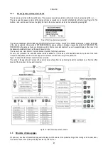
Power supply cable section in mm²
10 m
20 m
30 m
40 m
50 m
60 m
70 m
80 m
90 m
100 m
120 m
140 m
160 m
180 m
200 m
4 A
1,5
1,5
1,5
1,5
2,5
2,5
2,5
2,5
4
4
4
6
6
6
10
8 A
1,5
1,5
2,5
2,5
4
4
6
6
6
10
10
10
10
16
16
12 A
1,5
2,5
4
4
6
6
10
10
10
10
16
16
16
16 A
2,5
2,5
4
6
10
10
10
10
16
16
16
20 A
4
4
6
10
10
10
16
16
16
16
24 A
4
4
6
10
10
16
16
16
28 A
6
6
10
10
16
16
16
Data concerning 3-core PVC cables (phase earth)
Table 5: Single phase line power cable section
2.2.1.2
Connection to the power line MCE-150/P – MCE-110/P – MCE-55/P – MCE-30/P
The inverter must be connected to the 3-phase power line by means of a 4-core cable (3 earth) The relative line specifications
must correspond to those shown in Table 1.
The input terminals are those marked with the text RST and an arrow pointing towards the terminals; see
Figure 3. The section, type and laying of cables for inverter power supply and electric pump connections must be selected in compliance
with current standards. Table 4 provides indications on the cable section to be used. The table refers to cables in PVC with 4 wires (3
earth) with the minimum recommended section based on the current and length of cable.
The current supply to the inverter can normally be calculated (taking a safety margin into account) as 1/8 of the current absorbed by
the pump.
Although the inverter is already equipped with internal safety devices, the installation of a suitably sized thermal magnetic circuit
breaker is recommended.
If the entire power range available is used, for specific information on the current to be used when choosing cables and the thermal
magnetic circuit breaker, refer to Table 4.
Table 1c also indicates the sizes of thermal magnetic circuit breakers to be used, according to the current absorption.
2.2.1.3
Electrical connections to the pump
The connection between the inverter and the electropump must be made with a 4-core cable (3 earth). The characteristics
of the connected electropump must be able to satisfy the indications in Table 1.
The output terminals are those marked with the text UVW and an arrow pointing away from the terminals; see Figure 3.
The section, type and laying of the cables for connection to the electropump must be chosen according to the regulations in force.
Table 4 supplies an indication on the section of the cable to be used. The table refers to 4-core PVC cables (3 earth) and
gives the recommended minimum section with relation to the current and the length of the cable.
The electropump current is generally specified on the motor data plate.
The rated voltage of the electric pump must be the same as the supply voltage of the inverter.
The rated frequency of the electric pump can be set via the display according to the specifications on the manufacturer’s dataplate.
For example, the inverter can also be powered at 50 [Hz] with control of an electric pump at 60 [Hz] - nominal (provided that the pump
is declared as compatible for this frequency).
For special applications, pumps are also available with frequency up to 200 [Hz].
The utility connected to the inverter must not absorb current in excess of the maximum values specified in Table 1.
Check the dataplates and type of motor connection (star or delta) used to ensure compliance with the above conditions.
2.2.1.4
Electrical connections to the electric pump MCE-22/P – MCE-15/P – MCE-11/P
Models MCE 22/P – MCE 15/P – MCE 11/P
require motor configuration for a three-phase voltage of 230V. This is normally obtained
by a delta configuration of the motor. See Figure 4.
Содержание MCE-150/P
Страница 308: ...306 IEC 60634 1...
Страница 309: ...307 1 6 1 1...
Страница 312: ...310 1 2 1 1 1 1 2 5 2 1 2 1 2...
Страница 313: ...311 2 1 1 2 1 2 L L L 2 2 4 2 15 2 2 1 1a...
Страница 314: ...312 2a 3a 4b 1b 127 240 240 480...
Страница 318: ...316 GP GI 6 6 4 6 6 5 7 A B C D...
Страница 320: ...318 9 4 20 7 4 20 PR 6 5 7 4 20 2 18 J5 GND 1 J5 GND o IN 11 J5 o OUT 7 J5 4 20 7 OUT 8 10 11 IN...
Страница 323: ...321 50 60 7 DC AC 50 60 8 6 2 1 5 36 36 12 3 3 3 3 2 13 9 10 8...
Страница 324: ...322 12 J5 I1 11 17 16 18 16 17 I2 11 15 16 18 15 16 I3 11 14 13 18 13 14 I4 11 12 13 8 12 13 10 10 I1 1 I2 3 I3 5 I4 10...
Страница 325: ...323 I1 F1 I1 6 6 13 2 I2 P2 6 6 13 3 I3 F3 6 6 13 4 I4 1 F4 6 6 13 5 10 GND 7 I1 I2 I3 I4...
Страница 326: ...324 3 13 64 X 128 4 MODE SET 11 SET 9 MODE 1 SET 11 3 EEprom SET 6 SET MODE 3 1 11...
Страница 327: ...325 3 2 1 2 3 2 1 MODE SET MODE 10 2 2 5 5 5 2 2 12...
Страница 329: ...327 12 SET 14 15 13 15 3 3...
Страница 330: ...328 12 14 16 GO SB BL LP HP EC OC OF SC OT OB BP NC F1 F3 F4 P1 1 P2 2 P3 3 P4 4 E0 E16 0 16 EE EEprom WARN...
Страница 331: ...329 15 14 3 4 PW 6 6 16 GO SB...
Страница 332: ...330 4 4 1 Link 8 4 2 4 2 1 Link Link 15...
Страница 333: ...331 17 Link 4 2 2 0 5V 4 20 A 0 4 2 2 1 FI FI 4 2 2 2 FZ 6 5 9 1 4 2 2 3 0 5 4 20 A 0 5 0...
Страница 336: ...334 4 4 2 2 4 2 5 4 5 ET 6 6 9 FL 4 5 1 4 5 1 1 ET ET ET ET 0 ET 6 6 9 4 5 1 2 23 23...
Страница 339: ...337 FZ FZ 2 35 FZ 37 FZ FZ FZ FZ FI 0 FZ FZ 0 5 1 7 6 GI GP FL TB...
Страница 341: ...339 6 6 1 MODE MODE 6 1 1 FR 6 1 2 VP 6 1 3 C1 A C1 RC 6 5 1 6 1 4 PO PO 6 1 5 SM 15 SB F 17 SM 15 F Sb RC A...
Страница 342: ...340 SM 6 1 6 VE 26 1 0 S 5 6 2 2 SET MODE 6 2 1 VF 6 2 2 TE 6 2 3 BT 6 2 4 FF FF x y x y x 1 x y 64 RF 6 2 5 CT 6 2 6 LA...
Страница 362: ...360 OC 10 6 OF 10 6 33 8 8 1 PMW 4 2 8 2 8 3 8 3 SET EE EEprom FLASH...
Страница 548: ...546 IEC 364 1 inverter...
Страница 549: ...547 1 Inverter inverter inverter 6 inverter 1 1...
Страница 552: ...550 1 2 1 1 inverter inverter 1 1 2 5 inverter inverter 2 1 inverter inverter 2 1 2 C...
Страница 554: ...552 2a 3a 4b...
Страница 558: ...556 GP GI 6 6 4 6 6 5 inverter 7 A B C D...
Страница 563: ...561 I 2 15 16 I 3 13 14 I 4 12 13 50 60 Hz 7 DC V AC 50 60 Hz Vrms V 8 6 V 2 1 5 V 36 36 12V mA 3 3 3 3 mm 2 13 9 10 8...
Страница 564: ...562 11 J5 pin Pin I1 11 17 16 18 16 17 I2 11 15 16 18 15 16 I3 11 14 13 18 13 14 I4 11 12 13 8 12 13 10...
Страница 565: ...563 10 I1 1 I2 3 I3 5 I4 10 I1 F1 I1 6 6 13 2 I2 P2 6 6 13 3 I3 F3 6 6 13 4 I4 1 F4 6 6 13 5 10 V GND 7 1 2 3 4...
Страница 566: ...564 3 12 oled 64 X 128 4 MODE SET 11 SET inverter 9 MODE 1 SET 11 3 EEprom SET 6 SET MODE 3 1 11...
Страница 567: ...565 3 2 1 2 3 2 1 MODE SET Setpoint MODE 10 ONOMA TOY MENOY 2 Setpoint 2 5 5 5 2 2 12...
Страница 569: ...567 3 2 2 12 SET 13 MAIN UTENTE MONITOR MENU ESTESO MENU ESTESO PASSWORD PASSWORD Setpoint 15 13 14...
Страница 571: ...569 15 15 14 3 4 Password inverter password password inverter password PW 6 6 16 GO SB FAULT...
Страница 728: ...726 IEC 364 1 1...
Страница 729: ...727 1 1...
Страница 732: ...730 1 2 1 1 1 2 5 2 1 2 1 2 C...
Страница 733: ...731 2 1 1 0 2 1 2 L L L 2 2 4 2 15 2 2 1 1...
Страница 734: ...732 2a 3a 4b...
Страница 738: ...736 GP GI 6 6 4 6 6 5 7 2 2 3 2 Press Flow 6 A B C D...
Страница 743: ...741 DC AC 50 60 Hz 7 DC V AC 50 60 Hz Vrms V 8 6 V 2 1 5 V 36 36 12V A 3 3 3 3 2 13 8 10 8...
Страница 744: ...742 12 J5 I1 11 17 16 18 16 17 I2 11 15 16 18 15 16 I3 11 14 13 18 13 14 I4 11 12 13 8 12 13 9...
Страница 746: ...744 3 13 Oled 64 X 128 4 MODE SET 11 SET or 9 MODE 1 SET 10 3 EEprom SET SET or MODE...
Страница 750: ...748 12 13 16 GO SB BL LP HP EC OC OF SC OT OB BP NC F1 F3 F4 P1 1 P2 2 P3 3 P4 4 E E0 E16 0 16 EE EEprom...
Страница 751: ...749 14 14 3 4 PW 6 6 16 GO SB FAULT...
Страница 752: ...750 4 4 1 Link 8 4 2 4 2 1 Link Link 15...
Страница 760: ...758 6 6 1 MODE MODE 6 1 1 FR Hz 6 1 2 VP psi 6 1 3 C1 A C1 RC 6 5 1 6 1 4 PO kW PO 6 1 5 SM 3 SB F 16 SM 15 F Sb RC A...
Страница 761: ...759 SM 6 1 6 VE 26 1 0 S 5 6 2 SET 2 MODE 6 2 1 VF 6 2 2 TE 6 2 3 BT 6 2 4 FF x y FF x y x 1 x y 64 RF 6 2 5 CT 6 2 6 LA...
Страница 777: ...775 FF 6 6 16 PW PW 0 PW 0 XXXX PW 10 PW 2 10 0 7 3 6 6 16 1 PW PW PW 0 PW 0 0 PW all PW PW PW 0...
Страница 966: ...964 IEC 60634 1...
Страница 967: ...965 1 6 1 1...
Страница 970: ...968 1 2 5 2 1 2 1 2 2 1 1...
Страница 971: ...969 2 1 2 L L L 2 2 4 2 15 2 2 1 1a 1a...
Страница 972: ...970 2a 2b 1b 127 240 240 480 3 6 1b MCE 22 P MCE 15 P MCE 11 P V 230 V 230 V 230 V A 10 5 8 0 6 5...
Страница 976: ...974 3 2 2 3 2 Press Flow 6 A B C D...
Страница 978: ...976 7 4 20 5 4 20 PR 6 5 7 4 20 2 18 J5 GND 1 J5 GND o IN 11 J5 o OUT 7 J5 4 20 7 OUT 8 10 11 IN...
Страница 981: ...979 50 60 7 DC AC 50 60 8 6 2 1 5 36 36 12 3 3 3 3 2 13 2 10 8...
Страница 982: ...980 5 J5 I1 11 17 16 18 16 17 I2 11 15 16 18 15 16 I3 11 14 13 18 13 14 I4 11 12 13 8 12 13 8...
Страница 984: ...982 SET 9 3 EEprom SET 6 SET MODE 3 1 11 3 2 1 2 3 2 1 MODE SET MODE 10 2 2 5 5...
Страница 986: ...984 4 3 2 2 12 SET 7 15 13...
Страница 987: ...985 8 3 3 psi 12 GO SB BL LP HP EC...
Страница 988: ...986 5 9 6 14 3 4 OC OF SC OT OB BP NC F1 F3 F4 P1 1 P2 2 P3 3 P4 4 E0 E16 0 16 EE EEprom WARN GO SB FAULT...
Страница 989: ...987 PW 6 6 16 4 4 1 Link 8 4 2 4 2 1 Link Link 15...
Страница 990: ...988 10 Link 4 2 2 0 5V 4 20 0 1 4 2 2 1 FI Fl 4 2 2 2 FZ 6 5 9 1 4 2 2 3 0 5 4 20 0 5 0 5 4 20 2 2 3 1...
Страница 993: ...991 4 4 2 2 4 2 5 4 5 ET 6 6 9 FL 4 5 1 4 5 1 1 ET ET ET ET 0 ET 6 6 9 4 5 1 2 23 23...
Страница 998: ...996 SB F 8 SM 15 Sb F RC A SM 6 1 6 VE 26 1 0 S 5 6 2 2 SET MODE 6 2 1 VF 6 2 2 TE 6 2 3 BT 6 2 4 FF FF x y x y...
Страница 1018: ...1016 BL 10 6 24 24 30 LP HP OT TE 100 C 85 C OB BT 120 C 100 C OC 10 6 OF 10 6 20 8 8 1 PMW 4 2 8 2 8 3 8 3 SET EE EEPROM FLASH...
Страница 1020: ......
Страница 1021: ......
Страница 1022: ......
Страница 1023: ......


