


xStack
®
DGS-3600 Series Layer 3 Managed Gigabit Ethernet Sw itch
17
Connect to RPS
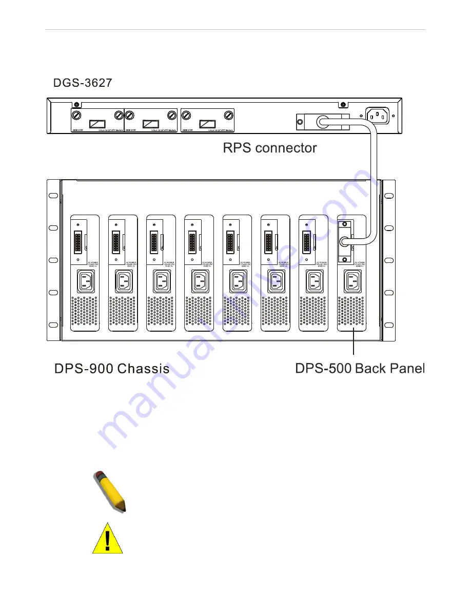
The DPS-500 is connected to the Master Switch using a 14-pin DC power cable. A standard, three-pronged AC power cable
connects the redundant power supply to the main power source.
Figure 2 - 11. The DGS-3627 with the DPS-500 chassis RPS
1.
Insert one end of the 14-pin DC power cable into the receptacle on the switch and the other end into the redundant power
supply.
2.
Using a standard AC power cable, connect the redundant power supply to the main AC power source. A green LED on the
front of the DPS-500 will glow to indicate a successful connection.
3.
Re-connect the switch to the AC power source. A LED indicator will show that a redundant power supply is now in
operation.
4.
No change in switch configuration is necessary for this installation.
NOTE:
See the DPS-500 documentation for more information.
CAUTION:
Do not use the Switch with any redundant power system other
than the DPS-500.
Содержание xStack DGS-3600 Series
Страница 1: ...xStack DGS 3600 Series Layer 3 Managed Gigabit Ethernet Switch i ...
Страница 66: ......


