background image

3  Getting Started


D-Link Smart Managed Switch User Manual


10.x.y.z

 (where x/y is a number between 0 and  254 and z is a number between 1 and  254), and a subnet 

mask of 

255.0.0.0

. To launch the web interface, simply open any compatible web browser, enter 

10.90.90.90


(the factory-default IP address) in the address bar, and press ENTER. 


Figure 3.2 - Enter the IP address 10.90.90.90 in the web browser 


NOTE:

 The Switch’s factory default IP address is 

10.90.90.90 with a subnet mask of 255.0.0.0 and 
a default gateway of 0.0.0.0. 


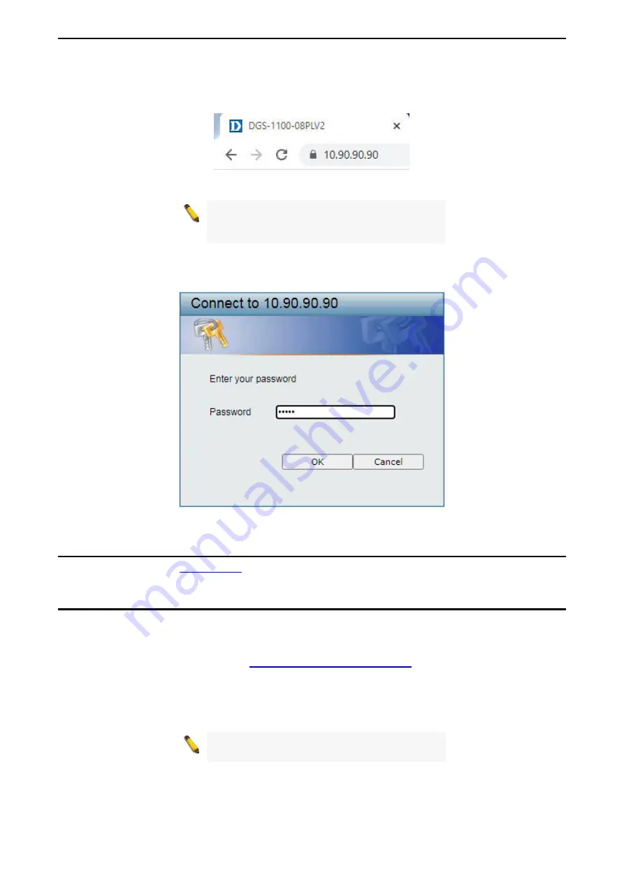
This will automatically load the web configuration in your web browser. 

When prompted to log in, enter the default password admin and press 

OK

 to continue. 


Figure 3.3 - Logon Dialog Box 


Web-based Management 

Please refer to Chapter 

Configuration

 for detailed instructions. 


D-Link Network Assistant (DNA) 

D-Link Network Assistant (DNA) is a program that is used to discover switches which are in the same Layer 
2 network segment as your PC. You can download the DNA App from the D-Link official website. 


1. 

Go to the D-Link official website at: 

https://tools.dlink.com/intro/dna/

. 

2. 

Click the 

Free Download

 button to go the the Download window. 

3. 

Click the 

Download

 button to download the DNA installer file to your local hard drive. 

4. 

Run the DNA installer file and follow the on-screen instructions to complete the installation. 


NOTE:

 Refer to D-Link Network Assistant (DNA) 

User Guide for more detail. 


Содержание EasySmart DGS-1100-08PLV2

Страница 1: ......

Страница 2: ......

Страница 3: ...ased Management 9 Tool Bar Save 10 Save Configuration 10 Tool Bar Tools 10 Reboot System 10 Reset 10 Firmware Backup and Upgrade 10 Configuration Backup and Restore 11 Tool Bar Help 12 Function Tree 12 Device Information 12 System System Information Settings System Information 13 System System Information Settings IPv4 Interface 13 System Port configuration Port Settings 14 System Port Configurati...

Страница 4: ...ettings 30 L2 Features Loopback Detection 31 L2 Features Link Aggregation 32 L2 Features L2 Multicast Control IGMP Snooping IGMP Snooping Settings 33 L2 Features L2 Multicast Control IGMP Snooping IGMP Snooping Group Settings 34 QoS 802 1p DSCP Default Priority 34 QoS Port Rate Limiting 36 Security Traffic Segmentation 36 Security Storm Control 37 Security Port Security 37 OAM Cable Diagnostics 38...

Страница 5: ...technologies refer to terms switch bridge and switching hubs interchangeably and both are commonly accepted for Ethernet switches A NOTE indicates important information that helps a better use of the device A CAUTION indicates potential property damage or personal injury Copyright and Trademarks Information in this document is subjected to change without notice 2020 D Link Corporation All rights r...

Страница 6: ...the video traffic from pre defined IP surveillance devices to an assigned VLAN with higher priority so it can be separated from normal data traffic Network Security Storm Control can help to keep the network from being overwhelmed by abnormal traffic Meanwhile Port Security provides administrators with an additional layer of security to prevent unauthorized users from accessing the network Versati...

Страница 7: ...o PD is connected CAUTION The equipment power supply cord shall be connected to a socket outlet with earthing connection Rear Panel Figure 1 2 DGS 1100 08PLV2 Rear Panel Power Input for a 54V 1 67A AC adapter Kensington Lock This is used to attach a physical Kensington security lock GND This is used to connect the Switch to ground LED Indicators The Switches feature LED indicators for Power and Li...

Страница 8: ...tes data is being processed on this port at 1000 Mbps Solid Amber Indicates there is a 10 100 Mbps connection on this port Blinking Amber Indicates data is being processed on this port at 10 100 Mbps Light off Indicates there is no active link on this port Per PoE Port PoE Green Amber Solid Green PD is connected and power is supplied Solid Amber PD is connected but failure occured The PSE cannot p...

Страница 9: ...pation and adequate ventilation around the switch Do not place heavy objects on the switch Desktop or Shelf Installation DGS 1100 08PLV2 comes with a strip of four adhesive rubber pads that can be placed on the bottom of the device to prevent the device from damaging the desktop or shelf it is places on To attach the rubber pads simply remove them from the adhesive strip and stick one pad on each ...

Страница 10: ...itch onto the screws to secure the device to the wall Mounting on a wood wall Step 1 Drive the included screws into a wood wall Step 2 Hook the mounting keyholes on the back of the Switch onto the screws to secure the device to the wall Figure 2 2 Wall mount installation Metal screw M7 type Length 16 mm Number of screws 2 ...

Страница 11: ...ss of your PC making it easier to simultaneously initialize multiple D Link Managed Switches Please refer to the following installation instructions for the Web interface and the D Link Network Assistant DNA Using the Web based Management Interface After successfully installing the Switch you can configure and monitor the Switch through the web based management tool using any compatible web browse...

Страница 12: ...ted to log in enter the default password admin and press OK to continue Figure 3 3 Logon Dialog Box Web based Management Please refer to Chapter 4 Configuration for detailed instructions D Link Network Assistant DNA D Link Network Assistant DNA is a program that is used to discover switches which are in the same Layer 2 network segment as your PC You can download the DNA App from the D Link offici...

Страница 13: ... Bar provides a quick and convenient way for accessing essential functions such as firmware upgrades and basic settings When clicking a section or subsection in the function tree all the settings of that section are displayed in the Main Configuration Window In the upper right corner of the window the current login username and IP address are displayed Next to the IP address is the Logout button C...

Страница 14: ... Reboot System This option provides a safe way to reboot the system Click Yes to save the current settings or click No to discard the current settings Click Reboot to restart the Switch Figure 4 5 Tools Reboot System Reset Provide a safe reset option for the Switch Depending on the chosen reset option some or all configuration settings stored in the device s flash memory will be reset to factory d...

Страница 15: ...rmware Backup and Upgrade Upgrade Click Choose File to browse for a compatible firmware file on your hard drive Click Upgrade to update the device s firmware using the selected firmware file Click Reboot to cancel the firmware upgrade and reboot the device NOTE Do not disconnect the PC or remove the power cord from device until the upgrade completes The Switch may crash if the firmware update is i...

Страница 16: ...t Site leads to the D Link website where you can find online resources such as updated firmware images User Guide can offer an immediate reference for the feature definition or configuration guide Figure 4 12 Online Help Function Tree All configuration options of the Switch are accessed through the treeview on the left window Click the setup item that you want to configure The following sections p...

Страница 17: ...ation Specify the system location of the Switch System Contact Specify the system contact of the Switch Web Session Timeout 60 36000 The Web Session Timeout controls the idle time out period for security purposes when there is no activity in the web interface within the specified time out period If the current session times out expires the user is required to log into the web management interface ...

Страница 18: ...s 0 0 0 0 DHCP Retry Time 5 120 Specify the number of attempts to assign an IP address through a DHCP server The range is from 5 to 120 times and the default setting is 7 times Table 4 2 Click Apply to make the configurations take effect System Port configuration Port Settings In Port Settings the status of all ports can be monitored and configured Figure 4 17 System Port Configuration Port Settin...

Страница 19: ...tagged This function is disabled by default Click Enabled and Apply to turn on the jumbo frame support Figure 4 18 System Port Configuration Jumbo Frame System PoE PoE System The PoE System window will display the PoE status including System Budget Power Support Total Power Remainder Power and the ratio of system power supply Figure 4 19 System PoE PoE System The fields that can be configured are ...

Страница 20: ... W IEEE 802 3af defined that the PSE provides power according to the following classification Class Usage Minimum Power Levels Output at the PSE Maximum Power Levels at the PD 0 Default 15 4 W 0 44 to 12 95 W 1 Optional 4 0 W 0 44 to 3 84 W 2 Optional 7 0 W 3 84 to 6 49 W 3 Optional 15 4 W 6 49 to 12 95 W 4 Optional Treat as Calss 0 Reserved for future use IEEE 802 3at defined that the PSE provide...

Страница 21: ...ox and input the power budget to manually assign an upper limit of port power budget on designated port s Table 4 5 Click Apply to make the configurations take effect Click Refresh button to update the port PoE status information NOTE For the PoE Port Settings table if the classification was shown as Legacy PD it will be classified to non AF PD or Legacy PD NOTE The Switch conforms to IEEE 802 3af...

Страница 22: ...sired to take when PD host is unreachable The default action is Reboot Table 4 6 Click Apply to make the configurations take effect Click Refresh button to update the information Management Password Access Control The Password Access Control window allows the user to configure the access password of the Switch Figure 4 22 Management Password Access Control The fields that can be configured are des...

Страница 23: ...ure to enable authentication traps When a client device fails to authenticate with the SNMP server and authentication trap will be sent to the management station Port Link Up Check this feature to enable Link Up traps Whenever a device changes status from link down to link up it will send a Link Up trap to the management station Port Link Down Check this feature to enable Link Down traps Whenever ...

Страница 24: ...te SNMP managers access to MIB objects in the Switch s SNMP agent Table 4 9 Click Apply to create a new SNMP community Management SNMP SNMP Host Settings This window is used to configure the recipients of the SNMP notifications Figure 4 25 Management SNMP SNMP Host Settings The fields that can be configured are described below Item Description Host IPv4 Address Specify the IPv4 address of the SNMP...

Страница 25: ... FDB The fields that can be configured are described below Item Description Port Drop The selection of the port number on which the MAC address entered resides This option could also drop the MAC address from the unicast static FDB When selecting Port select the switch port number Port Number Select the port number used here when Port is selected in the previous drop down list VID Enter the VLAN I...

Страница 26: ... is 01 XX XX XX XX XX Table 4 13 Click Apply to make the configurations take effect Click Delete All to delete all the entries found in the display table Click Delete to remove the corresponding entry L2 Features FDB MAC Address Table Settings This window allows user to view and configure the MAC address learning function Figure 4 29 L2 Features FDB MAC Address Table Settings The fields that can b...

Страница 27: ... Click Clean All to clear the selected dynamic MAC addresses Click the Corresponding check box es in the Add column to select the specific dynamic MAC address es Select the page number in the Page drop down list to navigate to a specific page when multiple pages exist Click Pre Page to go to the previous page when multiple pages exist Click Next Page to go to the next page when multiple pages exis...

Страница 28: ...e to remove the VLAN group To create a new VLAN group click Add VID and the following will be displayed Figure 4 32 L2 Features VLAN 802 1Q VLAN Add VID The fields that can be configured for 802 1Q VLAN are described below Item Description VID Enter the VID to be created VLAN Name Enter the VLAN name for the VID to be created Port Assign ports as Untagged Tagged or Not Member Click All to select a...

Страница 29: ...he fields that can be configured are described below Item Description Port Based VLAN Select to enable or disable the Port Based VLAN function The default is Disabled Table 4 17 Click Apply to make the configurations take effect To enable the Port Based VLAN function click Enabled and Apply and the following will be displayed Figure 4 36 L2 Features VLAN Port Based VLAN Enabled Click Rename to ren...

Страница 30: ...the default VLAN to another VLAN This allows for more flexible network management There can only be one management VLAN at a time when this function is enabled Figure 4 38 L2 Features VLAN Management VLAN The fields that can be configured are described below Item Description Management VLAN Select to enable or disable the Management VLAN function The default is Disabled VID Select the VID to act a...

Страница 31: ...ffect L2 Features VLAN Surveillance VLAN Surveillance VLAN is a feature that allows you to place the video traffic from D Link IP cameras to an assigned VLAN to enhance the IP surveillance service With a higher priority and individual VLAN the quality and the security of surveillance traffic are guaranteed The Surveillance VLAN function will check the source MAC address on the incoming packets If ...

Страница 32: ...ponents are Video Management Server VMS VMS Client Video Encoder Network Storage and Other IP Surveillance Devices Usually VMS and VMS clients are necessary components for an IP surveillance service Description Enter a description for the component MAC Address Enter a MAC address of the component Table 4 20 Click Apply to make the configurations take effect Click Add to create a new device for Sur...

Страница 33: ... values including 3COM Cisco Veritel Pingtel Siemens NEC Phillips Huawei3COM and Avaya User defined OUI The user can manually create a Telephony OUI with a description The maximum number of user defined OUIs is 5 Table 4 21 Below is a list of the pre defined voice OUI s These cannot be used as a user defined OUI OUI Vendor Mnemonic Name 00 E0 BB 3COM 3com 00 03 6B Cisco cisco 00 E0 75 Veritel veri...

Страница 34: ...e State Select to enable or disable the Spanning Tree Protocol Spanning Tree Mode Spanning Tree Mode Select the STP mode The options to choose from are RSTP and STP STP Traps STP New Root Trap Select to enable or disable the STP new root trap option STP Topology Change Traps Select to enable or disable the STP topology change trap option Table 4 23 Click Apply to make the configurations take effec...

Страница 35: ...t will always wait for the forward time delay to change to the forwarding state In the Edge mode the port will directly change to the spanning tree forwarding state when a link up occurs without waiting for the forward time delay If the interface receives a BPDU later its operation state changes to the non port fast state The default option is Network Table 4 24 Click Apply to make the configurati...

Страница 36: ... a Loopback is detected The Loop Detection Recover Time can be set at 0 seconds or 60 to 255 seconds Entering 0 will disable the Loop Detection Recover Time The default is 60 seconds Loopback Detection Port Settings From Port To Port Select the range of ports to enable or disable Loopback Detection for State Enable or disable Loopback Detection for the specified range of ports Table 4 25 Click App...

Страница 37: ...2 Features L2 Multicast Control IGMP Snooping IGMP Snooping Settings With Internet Group Management Protocol IGMP snooping the Smart Managed Switch can make intelligent multicast forwarding decisions by examining the contents of each frame s Layer 2 MAC header By default IGMP is disabled If enabled the Smart Managed Switch can recognize IGMP queries and reports sent between network stations or dev...

Страница 38: ... Add to create a new IGMP Snooping group Click Delete to remove the corresponding IGMP Snooping group Click Delete All to remove all IGMP Snooping groups Click Refresh to renew the IGMP Snooping Groups Table information QoS 802 1p DSCP Default Priority Quality of Service QoS is an implementation of the IEEE 802 1p standard that allows network administrators to manage traffic for important function...

Страница 39: ...e the traffic based on the 802 1p priority in the VLAN tag or the DSCP Differentiated Services Code Point priority in the IP header Only one mechanism is selected to prioritize the packets at a time Queuing mechanism Specify the queuing mechanism the option are Strict Priority Denoting a Strict scheduling will set the highest queue to be emptied first while the other queues will follow the weighte...

Страница 40: ...d to configure the transfer speed limit for a selection of ports Figure 4 50 QoS Port Rate Limiting The fields that can be configured are described below Item Description From Port To Port Specify a range of ports to be configured Direction Select the direction option Options to choose from are Input This configures the transfer speed limit for ingress traffic Output This configures the transfer s...

Страница 41: ...ts Once a packet storm has been detected the Switch will drop incoming packets until the storm has subsided Figure 4 52 Security Storm Control The fields that can be configured are described below Item Description Storm Control Status Specify to enable or disable the storm control function Storm Control Specify the type of controlled packets Options are Broadcast Only Multicast Broadcast and Multi...

Страница 42: ...MAC address table Select Disabled to disable Port Security on the corresponding port s Max Learning Address Define the maximum number of MAC addresses that can be associated with the corresponding port This ranges from 0 to 4160 Table 4 33 Click Apply to make the configurations take effect OAM Cable Diagnostics The Cable Diagnostics is designed primarily for administrators and customer service rep...

Страница 43: ...ort and test again Cable Fault Distance meters Indicates the distance of the cable fault from the Switch port If the cable is less than 2 meters it will show No Cable whether the cable is connected to the port or not Table 4 34 Monitoring Statistics Port Counters This window displays the status of each port s packet count Figure 4 56 Monitoring Statistics Port Counters Click Refresh to renew the p...

Страница 44: ...ansmitted from the source port s and forwards it to the Target Port Both Duplicate both the data transmitted from and data sent to the source port s and forwards all the data to the assigned Target Port Source Select the range of ports to be the source port and Frame Type to be mirrored Table 4 35 Click Apply to add the newly configured mirror entry based on the information entered Green EEE The E...

Страница 45: ...ielded twisted pair UTP cabling a flexible foundation for the next generation of network technology products will be created This will outfit your network with a powerful 1000 Mbps capable backbone server connection Fast Ethernet Technology The growing importance of LANs and the increasing complexity of desktop computing applications are fueling the need for high performance networks A number of h...

Страница 46: ... duplex 1000BASE T only supports full duplex IEEE 802 3x Flow control supports in the full duplex mode Back Pressure supports in the half duplex mode Support auto MDI MDIX Support auto negotiation for each port 10 100 1000Mbps PoE Ports Standard Compliance IEEE 802 3af PSE 15 W IEEE 802 3at PSE 30 W Physical Environment Dimensions 190 0 x 120 0 x 38 0 mm Weights 0 6 kg Power Supply DC input 54 V 1...

Страница 47: ...tenna Increase the separation between the equipment and receiver Connect the equipment into an outlet on a circuit different from that to which the receiver is connected Consult the dealer or an experienced radio TV technician for help Non modification Statement Any changes or modifications not expressly approved by the party responsible for compliance could void the user s authority to operate th...

Страница 48: ...ich ein trockenes fusselfreies Tuch CONSIGNES DE SÉCURITÉ Les consignes générales de sécurité ci après sont fournies afin d assurer votre sécurité personnelle et de protéger le produit d éventuels dommages Veuillez consulter les consignes d utilisation du produit pour plus de détails L électricité statique peut endommager les composants électroniques Déchargez l électricité statique de votre corps...

Страница 49: ... con humedad o condensación elevadas a menos que el producto esté clasificado específicamente para aplicación en exteriores Mantenga el producto alejado de los radiadores y de otras fuentes de calor Desenchufe siempre el producto de la alimentación de red antes de limpiarlo y utilice solo un paño seco sin pelusa VEILIGHEIDSINFORMATIE De volgende algemene veiligheidsinformatie werd verstrekt om uw ...

Страница 50: ...ses Symbol auf dem Produkt oder der Verpackung weist darauf hin dass dieses Produkt gemäß bestehender örtlicher Gesetze und Vorschriften nicht über den normalen Hausmüll entsorgt werden sollte sondern einer Wiederverwertung zuzuführen ist Bringen Sie es bitte zu einer von Ihrer Kommunalbehörde entsprechend amtlich ausgewiesenen Sammelstelle sobald das Produkt das Ende seiner Nutzungsdauer erreicht...

Страница 51: ... llegado al fin de su vida útil algunos de ellos aceptan recogerlos de forma gratuita Al reciclar el producto y su embalaje de esta forma contribuye a preservar el medio ambiente y a proteger la salud de los seres humanos D Link y el medio ambiente En D Link comprendemos y estamos comprometidos con la reducción del impacto que puedan tener nuestras actividades y nuestros productos en el medio ambi...

Страница 52: ...kelen of uit de stekker te halen wanneer u ze niet gebruikt Door dit te doen bespaart u energie en beperkt u de CO2 emissies Breng een bezoek aan www dlinkgreen com voor meer informatie over onze milieuverantwoorde producten en verpakkingen POLSKI PL Ten symbol umieszczony na produkcie lub opakowaniu oznacza że zgodnie z miejscowym prawem i lokalnymi przepisami niniejszego produktu nie wolno wyrzu...

Страница 53: ... na adrese www dlinkgreen com MAGYAR HU Ez a szimbólum a terméken vagy a csomagoláson azt jelenti hogy a helyi törvényeknek és szabályoknak megfelelően ez a termék nem semmisíthető meg a háztartási hulladékkal együtt hanem újrahasznosításra kell küldeni Kérjük hogy a termék élettartamának elteltét követően vigye azt a helyi hatóság által kijelölt gyűjtőhelyre A termékek egyes helyeken ingyen elhel...

Страница 54: ...å bortskaffes som husholdningsaffald mens skal sendes til genbrug Indlever produktet til et indsamlingssted som angivet af de lokale myndigheder når det er nået til slutningen af dets levetid I nogle tilfælde vil produktet blive modtaget gratis Ved at indlevere produktet og dets emballage til genbrug på denne måde bidrager du til at beskytte miljøet og den menneskelige sundhed D Link og miljøet Ho...

Страница 55: ... och bygger D Link sina produkter för att de ska vara så miljövänliga som möjligt genom att använda återvinningsbara material med låg gifthalt i både produkter och förpackningar D Link rekommenderar att du alltid stänger av eller kopplar ur dina D Link produkter när du inte använder dem Genom att göra detta hjälper du till att spara energi och minska utsläpp av koldioxid För mer information om vår...

Страница 56: ......

Страница 57: ......

Отзывы: