


D-Link DGS-3212SR Layer 2 Gigabit Ethernet Switch
Section 4
Switch Stack Management
The DGS-3212SR switch can be used as a standalone high-capacity switch or be used in a stacked arrangement.
There are two hardware requirements to use the switch in a stacked group:
1. The proper module(s) must be installed. One or two DEM-540 Stacking modules must be installed in
order to use the switch in a stacked configuration. Read page 5 in Section 1 and page 12 in Section 2
for more information about stacking the DGS-3212SR switch.
2. Slave switch units in a stacked switch group must be uniform in type and model, furthermore they must
be one of the switch models intended for use with the DGS-3212SR, namely the DES-3226S/SR,
DES3326S or other DGS-3212SR switches.
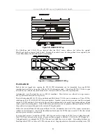
One stacking module can be installed to stack up to 4 additional slave switch units or two modules can be
installed to stack up to 8 additional slave switch units. Please read the relevant information in Sections 1 and 2
for more information.
Stacking Information
To change a switch’s default stacking configuration (for example, the order in the stack), you must use the
console Command Line Interface.
The number of switches in the switch stack (up to 5
−
total) are displayed in the upper right-hand corner of your
web-browser. The icons are in the same order as their respective Unit numbers, with the Unit 1 switch
corresponding to the icon in the upper left-most corner of the icon group.
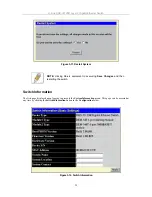
When the switches are properly interconnected through their optional Stacking Modules, information about the
resulting switch stack is displayed under the
Stack Information
link. This link is visible only when a switch
stack has been connected and the optional Stacking Modules are active.
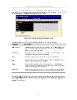
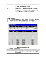
To view the stacking information, click on the Stacking Information link from the Basic Setup folder:
Figure 4-1. Stacking Information
ID
−
displays the switch’s order in the stack. The switch with a Unit ID of 1 is the Master Switch.
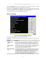
MAC Address
−
displays the unique address of the switch assigned by the factory.
Port Range
−
displays the total number of ports on the switch. Note that the stacking port is included in the total
count.
Mode
−
displays the method used to determine the stacking order of the switches in the switch stack.
35
Содержание DGS-3212SR
Страница 1: ...D Link DGS 3212SR High Density Layer 2 Modular Gigabit Ethernet Switch Manual...
Страница 21: ...D Link DGS 3212SR Layer 2 Gigabit Ethernet Switch Figure 2 3 Install switch in equipment rack 11...
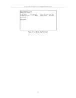
Страница 47: ...D Link DGS 3212SR Layer 2 Gigabit Ethernet Switch Figure 4 3 config stacking Command 37...