background image

DGS-1250 Series Gigabit Ethernet Smart Managed Switch Web UI Reference Guide 

211 

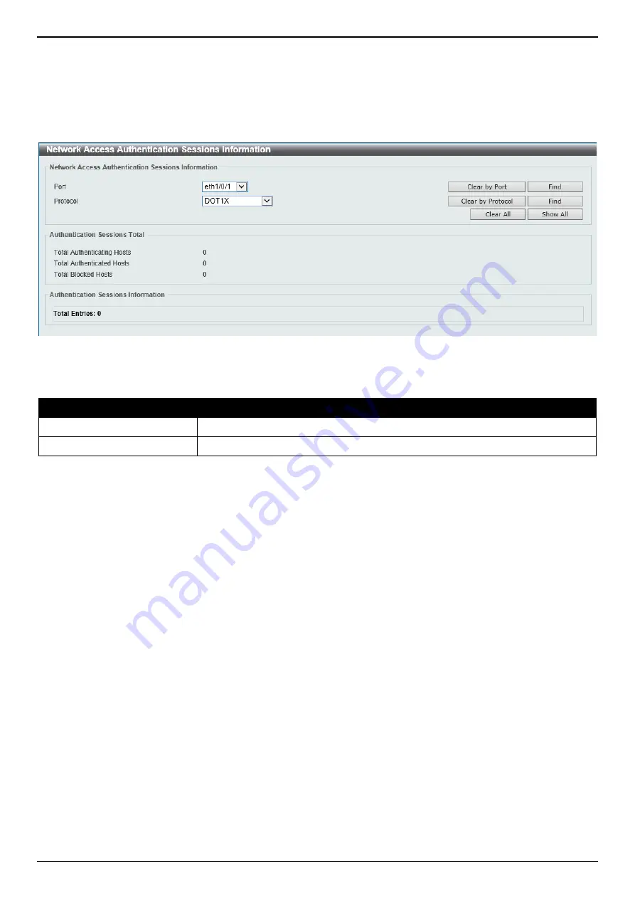
Network Access Authentication Sessions Information 

This window is used to view and clear the network access authentication session information. 


To view the following window, click 

Security > Network Access Authentication > Network Access Authentication 

Sessions Information

, as shown below: 


Figure 9-56 Network Access Authentication Sessions Information Window 


The fields that can be configured are described below: 

Parameter 

Description 

Port 

Select the port for the query here. 

Protocol 

Specifies that the protocol is 

DOT1X

 (IEEE 802.1X). 

Click the 

Clear by Port

 button to the clear the information based on the port selected. 

Click the 

Clear by Protocol

 button to the clear the information based on the protocol selected. 

Click the 

Clear All

 button to clear all the information in this table. 

Click the 

Find

 button to locate a specific entry based on the information entered. 

Click the 

Show All

 button to locate and display all the entries. 


Safeguard Engine 

Periodically, malicious hosts on the network will attack the Switch by utilizing packet flooding (ARP Storm) or other 
methods. These attacks may increase the Switch’s CPU load beyond its capability. To alleviate this problem, the 
Safeguard Engine function was added to the Switch’s software. 

The Safeguard Engine can help the overall operability of the Switch by minimizing the workload of the Switch while the 
attack is ongoing, thus making it capable to forward essential packets over its network in a limited bandwidth. 

If the CPU load rises above the rising threshold value, the Safeguard Engine function will be activated and the Switch 
will enter the exhausted mode. In the exhausted mode, the Switch will limit the bandwidth available for ARP and 
broadcast IP packets. If the CPU load falls below the falling threshold value, the Safeguard Engine will be deactivated 
and the Switch will exit the exhausted mode and enter the normal mode. 

Packets that are destined to the CPU can be classified into three groups. These groups, otherwise known as sub-
interfaces, are logical interfaces that the CPU will use to identify certain types of traffic. The three groups are 

Protocol

Manage

, and 

Route

Generally, the 

Protocol

 group should receive the highest priority when the Switch’s CPU processes received packets 

and the 

Route

 group should receive the lowest priority as the Switch’s CPU usually does get involved in the 

processing of routing packets. In the 

Protocol

 group, packets are protocol control packets identified by the router. In 

the 

Manage

 group, packets are destined to any router or system network management interface by means of 

Содержание DGS-1250 Series

Страница 1: ......

Страница 2: ...go are trademarks of the D Link Corporation Microsoft and Windows are registered trademarks of the Microsoft Corporation Other trademarks and trade names may be used in this document to refer to either as the entities claiming the marks and the names or their products D Link Corporation disclaims any proprietary interest in trademarks and trade names other than its own 2019 D Link Corporation All ...

Страница 3: ... Information 12 System Information Settings 13 Peripheral Settings 13 Port Configuration 14 Port Settings 14 Port Status 16 Port Auto Negotiation 16 Error Disable Settings 17 Jumbo Frame 18 Interface Description 19 PoE 19 PoE System 20 PoE Status 21 PoE Configuration 21 PoE Statistics 23 PoE Measurement 23 PoE LLDP Classification 24 System Log 24 System Log Settings 24 System Log Discriminator Set...

Страница 4: ... Relay 56 DHCP Auto Configuration 61 DNS 61 DNS Global Settings 61 DNS Name Server Settings 62 DNS Host Settings 63 File System 63 D Link Discovery Protocol 66 5 Layer 2 Features 67 FDB 67 Static FDB 67 MAC Address Table Settings 68 MAC Address Table 69 MAC Notification 70 VLAN 71 VLAN Configuration Wizard 71 802 1Q VLAN 74 VLAN Interface 75 Asymmetric VLAN 78 L2VLAN Interface Description 79 Auto ...

Страница 5: ...erface 127 IPv6 Interface 129 IPv4 Static Default Route 132 IPv4 Route Table 134 IPv6 Static Default Route 134 IPv6 Route Table 135 IP Multicast Routing Protocol 136 IPMC 136 IPv6MC 136 7 Quality of Service QoS 138 Basic Settings 138 Port Default CoS 138 Port Scheduler Method 139 Queue Settings 140 CoS to Queue Mapping 141 Port Rate Limiting 141 Queue Rate Limiting 142 Advanced Settings 143 DSCP M...

Страница 6: ... Global Settings 184 RADIUS Server Settings 184 RADIUS Group Server Settings 185 RADIUS Statistic 186 IMPB 187 IPv4 187 IPv6 199 DHCP Server Screening 205 DHCP Server Screening Global Settings 206 DHCP Server Screening Port Settings 207 ARP Spoofing Prevention 208 Network Access Authentication 208 Guest VLAN 208 Network Access Authentication Global Settings 209 Network Access Authentication Port S...

Страница 7: ...3 Toolbar 242 Save 242 Save Configuration 242 Tools 242 Firmware Upgrade Backup 242 Configuration Restore Backup 244 Certificate Key Restore Backup 247 Log Backup 249 Ping 250 Language Management 251 Reset 252 Reboot System 252 Wizard 253 Online Help 253 D Link Support Site 253 User Guide 253 Surveillance Mode 253 Logout 254 14 Surveillance Mode 255 Surveillance Overview 255 Surveillance Topology ...

Страница 8: ...ent 282 DHCPv6 Relay 283 DNS Resolver 283 DoS Prevention 283 Interface 284 LACP 284 LBD 284 LLDP MED 285 Login Logout CLI 286 MSTP Debug Enhancement 288 Peripheral 289 PoE 290 Port Security 290 Safeguard 290 SNMP 291 SSH 291 Storm Control 291 System Log Summary 291 Telnet 292 Voice VLAN 292 Web 293 Appendix B Trap Entries 294 802 1X 294 Authentication Fail 294 DHCP Server Screen Prevention 294 DoS...

Страница 9: ...art Managed Switch Web UI Reference Guide vii PoE 298 Port 299 Port Security 299 RMON 299 Safeguard 300 Start 300 Storm Control 300 System File 300 Appendix C RADIUS Attributes Assignment 302 Appendix D IETF RADIUS Attributes Support 303 ...

Страница 10: ...leshooting the Switch All the documents are available either from the CD bundled with this Switch or from the D Link website Other documents related to this Switch are DGS 1250 Series Hardware Installation Guide DGS 1250 Series CLI Reference Guide Conventions Convention Description Boldface Font Indicates a button a toolbar icon menu or menu item For example open the File menu and choose Cancel Us...

Страница 11: ...s document you should pay special attention to these indicators Each example below provides an explanatory remark regarding each type of indicator NOTE A note indicates important information that helps you make better use of your device NOTICE A notice indicates either potential damage to hardware or loss of data and tells you how to avoid the problem CAUTION A caution indicates a potential for pr...

Страница 12: ...rence Guide for more detailed information about the CLI SNMP based Management The Switch can be managed with an SNMP compatible Network Management System NMS The Switch supports SNMP v1 v2c v3 The SNMP agent on the Switch decodes the incoming SNMP messages and responds to requests with MIB objects stored in the database The SNMP agent on the Switch updates the MIB objects to generate statistics an...

Страница 13: ... 0 NOTE The factory default username and password is admin Figure 2 1 Displays entering the IP address in Internet Explorer After pressing the Enter key the following authentication window should appear as shown below Figure 2 2 Web UI Login Window Enter the User Name and Password in the corresponding fields and click the Login button After clicking the Login button the Web UI opens The management...

Страница 14: ...tor most of the software features on the Switch The Surveillance Mode is an additional web mode specifically designed to assist the user with surveillance features supported by the Switch NOTE The Web Mode can only be changed when one user session is connected to the Web UI of the Switch Figure 2 3 Web Mode The fields that can be configured are described below Parameter Description Standard Mode S...

Страница 15: ... surveillance devices for ONVIF cameras to be added to the Surveillance Mode Web UI automatically Figure 2 4 System IP Information The fields that can be configured are described below Parameter Description Static Select this option to manually assign and configure the IP address settings for the Switch DHCP Select this option to obtain IP address settings automatically from a DHCP server for the ...

Страница 16: ...ption User Name Select the user name here Password Type Select the password type here Options to choose from are None Specifies that no password will be configured for this user account Plain Text Specifies that the password for this user account will be in the plain text form Password After selecting Plain Text as the Password Type enter the password for the user account here Tick the Ignore the ...

Страница 17: ...ow Parameter Description SNMP Select to enable or disable the SNMP function here Tick the Ignore the wizard next time option to skip the Smart Wizard on the next login Click the Exit button to discard the changes made exit the Smart Wizard and continue to the Web UI Click the Back button to discard the changes made and return to the previous step Click the Apply Save button to accept the changes m...

Страница 18: ...r Description AREA 1 In this area a graphical near real time image of the front panel of the Switch is displayed with ports and expansion modules Port activity is displayed depending on the specified mode Some management functions like port monitoring are also accessible here Click the D Link logo to go to the D Link website AREA 2 In this area is a toolbar used to access functions like Save Tools...

Страница 19: ... the set of features AREA 4 In this area configuration and monitoring window frames are available based on the selections made in Area 3 Surveillance Mode After accessing the Web UI in the Surveillance Mode the following will be displayed Figure 2 8 Web UI Surveillance Mode Area Number Description AREA 1 In this area is a toolbar used to access functions like the Wizard Tools Save Help Online Help...

Страница 20: ... 3 There is also a search option in this area that can be used to search for specific feature keywords in the Web UI to find the link to the set of features AREA 3 In this area configuration and monitoring window frames are available based on the selections made in Area 2 The status of devices IP cameras and NVRs discovered on the switch will also be displayed in this area NOTE For more informatio...

Страница 21: ...nfiguration PoE System Log Time and SNTP Time Range Device Information In the Device Information section the user can view a list of basic information regarding the Switch It appears automatically when you log on to the Switch To return to the Device Information window after viewing other windows click the DGS 1250 28XMP link Figure 3 1 Device Information Window ...

Страница 22: ...m Contact Enter the contact information for the Switch here Click the Apply button to accept the changes made Peripheral Settings This window is used to display and configure the environment trap settings and environment temperature threshold settings To view the following window click System Peripheral Settings as shown below Figure 3 3 Peripheral Settings Window The fields that can be configured...

Страница 23: ...es made Port Configuration Port Settings This window is used to display and configure the Switch s port settings To view the following window click System Port Configuration Port Settings as shown below Figure 3 4 Port Settings Window The fields that can be configured are described below Parameter Description From Port To Port Select the appropriate port range used for the configuration here State...

Страница 24: ...er physical layer by a local source The Slave setting uses loop timing where the timing comes from a data stream received from the master If one connection is set for master the other side of the connection must be set for slave Any other configuration will result in a link down status for both ports Options to choose from are Auto Specifies that for copper ports auto negotiation will start to neg...

Страница 25: ... settings To view the following window click System Port Configuration Port Status as shown below Figure 3 5 Port Status Window Port Auto Negotiation This window is used to view detailed port auto negotiation information To view the following window click System Port Configuration Port Auto Negotiation as shown below Figure 3 6 Port Auto Negotiation Window ...

Страница 26: ...otification Rate Enter the notification rate value here This sets the number of traps per minute The packets that exceed the rate will be dropped The range is from 0 to 1000 The default value 0 indicates that an SNMP trap will be generated for every change of the error disabled state Click the Apply button to accept the changes made The fields that can be configured for Error Disable Recovery Sett...

Страница 27: ...mum frame size of up to 12 288 bytes To view the following window click System Port Configuration Jumbo Frame as shown below Figure 3 8 Jumbo Frame Window The fields that can be configured are described below Parameter Description From Port To Port Select the appropriate port range used for the configuration here Maximum Receive Frame Size Enter the maximum receive frame size value here This value...

Страница 28: ...P Ethernet cables The Switch follows the standard Power Sourcing Equipment PSE pin out Alternative A whereby power is sent out over pins 1 2 3 and 6 The Switches work with all D Link 802 3af capable devices The Switch includes the following PoE features Auto discovery recognizes the connection of a PD and automatically sends power to it The auto disable feature occurs under two conditions o If the...

Страница 29: ... send the corresponding standard notification The range is from 1 to 99 percent Policy Preempt Select this option to enable or disable the disconnection of the Powered Device PD that is power provisioned with a lower priority in order to release the power to the new connected PD with higher priority under power shortage conditions Trap State Select this option to enable or disable the sending of P...

Страница 30: ...opriate port range used for the configuration here Description Enter the text that describes the PD connected to a PoE interface The maximum length is 32 characters Click the Apply button to accept the changes made Click the Delete Description button to remove the description from the entry PoE Configuration This window is used to display and configure the PoE configuration settings NOTE If the Sw...

Страница 31: ...D Mode Select the power management mode for the PoE ports Options to choose from are Auto and Never Max Wattage When selecting Auto in the Mode drop down list this option appears Tick the check box and enter the maximum wattage of power that can be provisioned to the auto detected PD If the value is not entered the class of the PD automatically determines the maximum wattage that can be provisione...

Страница 32: ...oE PoE Statistics as shown below Figure 3 14 PoE Statistics Window Click the Clear All button to clear PoE statistics for all ports Click the Clear button to clear the PoE statistics for the corresponding port PoE Measurement This window is used to display the PoE measurement information on the Switch ports To view the following window click System PoE PoE Measurement as shown below Figure 3 15 Po...

Страница 33: ...igure 3 16 PoE LLDP Classification Window System Log System Log Settings This window is used to display and configure the system log settings To view the following window click System System Log System Log Settings as shown below Figure 3 17 System Log Settings Window The fields that can be configured for Log State are described below Parameter Description Log State Select the enable or disable th...

Страница 34: ...n 0 and 65535 seconds By default this value is 300 seconds Tick the Infinite option to disable the write delay feature Click the Apply button to accept the changes made System Log Discriminator Settings This window is used to display and configure the system log discriminator settings To view the following window click System System Log System Log Discriminator Settings as shown below Figure 3 18 ...

Страница 35: ...between 1024 and 65535 By default this value is 514 Severity Select the severity value of the type of information that will be logged Options to choose from are 0 Emergencies 1 Alerts 2 Critical 3 Errors 4 Warnings 5 Notifications 6 Informational and 7 Debugging Facility Select the facility number that will be logged here The range is from 0 to 23 Each facility number is associated with a specific...

Страница 36: ...nter the name of the discriminator that will be used to filter messages sent to the log server here This name can be up to 15 characters long Click the Apply button to accept the changes made Click the Delete button to delete the specified entry System Log This window is used to view and clear the system log To view the following window click System System Log System Log as shown below Figure 3 20...

Страница 37: ...ies displayed in the table Time and SNTP Clock Settings This window is used to display and configure the time settings for the Switch To view the following window click System Time and SNTP Clock Settings as shown below Figure 3 22 Clock Settings Window The fields that can be configured are described below Parameter Description Time Enter the current time in hours HH minutes MM and seconds SS here...

Страница 38: ...ured are described below Parameter Description Summer Time State Select the summer time setting Options to choose from are Disabled Recurring Setting and Date Setting Disabled Select to disable the summer time setting Recurring Setting Select to configure the summer time that should start and end on the specified weekday of the specified month Date Setting Select to configure the summer time that ...

Страница 39: ...ill end Offset Enter the number of minutes to add during summer time The default value is 60 The range of this offset is 30 60 90 and 120 The fields that can be configured in Date Settings are described below Parameter Description From Date of the Month Select date of the month that summer time will start From Month Select the month that summer time will start From Year Enter the year that the sum...

Страница 40: ...wn below Figure 3 24 SNTP Settings Window The fields that can be configured in SNTP Global Settings are described below Parameter Description SNTP State Select this option to enable or disable SNTP Poll Interval Enter the synchronizing interval in seconds The value is from 30 to 99999 seconds The default interval is 720 seconds Click the Apply button to accept the changes made The fields that can ...

Страница 41: ... of the week that will be used for this time profile Tick the Daily option to use this time profile for every day of the week Tick the End Week Day option to use this time profile from the starting day of the week until the end of the week From Time To Time Select the starting and ending time of the day that will be used for this time profile The first drop down menu selects the hour and the secon...

Страница 42: ...t Settings tab the following page will appear Figure 4 1 User Accounts Settings Window The fields that can be configured are described below Parameter Description User Name Enter the user account name here This name can be up to 32 characters long Password Type Select the password type for this user account here Options to choose from are None and Plain Text Password After selecting Plain Text as ...

Страница 43: ...ided between the management station and the network device In SNMPv1 and SNMPv2c user authentication is accomplished using community strings which function like passwords The remote user SNMP application and the Switch SNMP must use the same community string SNMP packets from any station that has not been authenticated are ignored dropped The default community strings for the Switch used for SNMPv...

Страница 44: ...es that alert network personnel of events that occur on the Switch The events can be as serious as a reboot someone accidentally turned the Switch off unplugged the Switch or less serious like a port status change The Switch generates traps and sends them to the trap recipient or network manager Typical traps include trap messages for Authentication Failure Topology Change and Broadcast Multicast ...

Страница 45: ... A linkDown trap is generated when the device recognizes that a one of the communication links is down Coldstart Tick this option to control the sending of SNMP coldStart notifications Warmstart Tick this option to control the sending of SNMP warmStart notifications Click the Apply button to accept the changes made SNMP Linkchange Trap Settings This window is used to display and configure the SNMP...

Страница 46: ...w Type Select the view type here Options to choose from are Included and Excluded Included Select to include this object in the list of objects that an SNMP manager can access Excluded Select to exclude this object from the list of objects that an SNMP manager can access Click the Add button to add a new entry based on the information entered Click the Delete button to remove the specified entry S...

Страница 47: ...ic string of up to 32 characters that is used to identify the group of MIB objects that a remote SNMP manager is allowed to access on the Switch The view name must exist in the SNMP View Table Access Right Select the access right here Options to choose from are Read Only and Read Write Read Only SNMP community members using the community string created can only read the contents of the MIBs on the...

Страница 48: ...ct to allow the group to use the SNMPv3 security model Write View Name Enter the write view name that the users of the group can access Security Level When selecting SNMPv3 in the User based Security Model drop down list this option is available NoAuthNoPriv Specify that there will be no authorization and no encryption of packets sent between the Switch and a remote SNMP manager AuthNoPriv Specify...

Страница 49: ...P engine ID string here This string can be up to 24 characters long Click the Default button to revert the engine ID to the default Click the Apply button to accept the changes made SNMP User Table Settings This window is used to display and configure the SNMP users that are currently configured on the Switch To view the following window click Management SNMP SNMP User Table Settings as shown belo...

Страница 50: ...ryption is in use based on the CBC DES DES 56 standard This field will require the user to enter a password or a key Password Enter the Priv Protocol password here For none this field will be disabled For DES56 the password must be between 8 and 16 characters long Auth Protocol by Key When selecting v3 in the SNMP Version drop down list and selecting Key in the SNMP V3 Encryption drop down list th...

Страница 51: ...to allow the group user to use the SNMPv3 security model Security Level When selecting SNMPv3 in the User based Security Model drop down list this option is available NoAuthNoPriv Specify that there will be no authorization and no encryption of packets sent between the Switch and a remote SNMP manager AuthNoPriv Specify that authorization will be required but there will be no encryption of packets...

Страница 52: ...eature Click the Apply button to accept the changes made RMON Statistics Settings This window is used to display and configure the RMON statistics on the specified port To view the following window click Management RMON RMON Statistics Settings as shown below Figure 4 12 RMON Statistics Settings Window The fields that can be configured are described below Parameter Description Port Select to choos...

Страница 53: ...ed below Parameter Description Port Select the port that will be used here Index Enter the history group table index The value is from 1 to 65535 Bucket Number Enter the number of buckets specified for the RMON collection history group of statistics The range is from 1 to 65535 The default value is 50 Interval Enter the time in seconds in each polling cycle The range is from 1 to 3600 Owner Enter ...

Страница 54: ...from 1 to 2147483648 seconds Variable Enter the object identifier of the variable to be sampled Type Select the monitoring type Options to choose from are Absolute and Delta Rising Threshold Enter the rising threshold value between 0 and 2147483647 Falling Threshold Enter the falling threshold value between 0 and 2147483647 Rising Event Number Enter the index of the event entry that is used to not...

Страница 55: ...ion Enter a description for the RMON event entry The string is up to 127 characters long Type Select the RMON event entry type Options to choose from are None Log Trap and Log and Trap Community Enter the community string The string can be up to 127 characters Owner Enter the owner string The string can be up to 127 characters Click the Add button to add a new entry based on the information entere...

Страница 56: ... Select to enable or disable the Telnet server feature here Port Enter the TCP port number used for Telnet management of the Switch The well known TCP port for the Telnet protocol is 23 The range is from 1 to 65535 Click the Apply button to accept the changes made The fields that can be configured in Web Settings are described below Parameter Description Web State Select this option to enable or d...

Страница 57: ...nsole Session Timeout Enter the console session timeout value here The range is from 0 to 1439 minutes Enter 0 to disable the timeout The default value is 3 minutes Select the Default option to use the default value Telnet Session Timeout Enter the Telnet session timeout value here The range is from 0 to 1439 minutes Enter 0 to disable the timeout The default value is 3 minutes Select the Default ...

Страница 58: ...hanges made DHCP Class Settings This window is used to display and configure the DHCP class and the DHCP option matching pattern for the DHCP class To view the following window click Management DHCP DHCP Class Settings as shown below Figure 4 22 DHCP Class Settings Window The fields that can be configured are described below Parameter Description Class Name Enter the DHCP class name with a maximum...

Страница 59: ...its will be matched If not specified all bits entered in the Hex field will be checked Click the Apply button to accept the changes made Click the Delete button to remove the specified entry Click the Back button to return to the previous window DHCP Relay DHCP Relay Global Settings This window is used to display and configure the global DHCP relay settings To view the following window click Manag...

Страница 60: ...s made Click the Edit button to modify the corresponding information of the specific DHCP pool Click the Delete button to remove the specified entry Enter a page number and click the Go button to navigate to a specific page when multiple pages exist After clicking the Edit button under Source the following window will appear Figure 4 26 DHCP Relay Pool Source Settings Window The fields that can be...

Страница 61: ...on to accept the changes made Click the Delete button to remove the specified entry Click the Back button to return to the previous window After clicking the Edit button under Class the following window will appear Figure 4 28 DHCP Relay Pool Class Settings Window The fields that can be configured are described below Parameter Description Class Name Select the DHCP class name Click the Apply butto...

Страница 62: ...y Information Settings This window is used to display and configure the DHCP relay information To view the following window click Management DHCP DHCP Relay DHCP Relay Information Settings as shown below Figure 4 30 DHCP Relay Information Settings Window The fields that can be configured are described below Parameter Description Information Trust All Select this option to enable or disable the DHC...

Страница 63: ...splay and configure the DHCP information format To view the following window click Management DHCP DHCP Relay DHCP Relay Information Option Format Settings as shown below Figure 4 31 DHCP Relay Information Option Format Settings Window The fields that can be configured in DHCP Relay Information Option Format Global are described below Parameter Description Information Format Remote ID Select the D...

Страница 64: ...ype or Circuit ID type here Value Enter the vendor defined string for Option 82 information in the remote circuit ID sub option here This string can be up to 32 characters long Click the Apply button to accept the changes made DHCP Local Relay VLAN Settings This window is used to display and configure local relay on a VLAN or a group of VLANs To view the following window click Management DHCP DHCP...

Страница 65: ...ions to choose from are ASCII and Hex ASCII Select to enter the ASCII string with a maximum of 128 characters in the text box HEX Select to enter the hexadecimal string with a maximum of 256 characters in the text box IPv6 DHCP Relay Remote ID Policy Select to choose Option 37 forwarding policy for the DHCPv6 relay agent Options to choose from are Keep and Drop Keep Select that the DHCPv6 request ...

Страница 66: ...ters o For example AABBCCDDEEFF Delimiter Number Specifies the delimiter number that will be used in the MAC address format here Options to choose from are 1 Specifies to use a single delimiter o For example AABBCC DDEEFF 2 Specifies to use two delimiters o For example AABB CCDD EEFF 5 Specifies to use multiple delimiters o For example AA BB CC DD EE FF Click the Apply button to accept the changes...

Страница 67: ...ing the Edit button enter the Option 82 format string here This string can be up to 251 characters long The following rules need to be considered This string can be a hexadecimal value an ASCII string or any combination of hexadecimal values and ASCII characters An ASCII string needs to be enclosed with quotation marks like Ethernet Any ASCII characters outside of the quotation marks will be inter...

Страница 68: ...This can be either an ASCII string or a hexadecimal value port Indicates the local port number This can be either an ASCII string or a hexadecimal value svlan Indicates the outer VLAN ID This can be either an ASCII string or a hexadecimal value cvlan Indicates the inner VLAN ID This can be either an ASCII string or a hexadecimal value Indicates the end of the formatted key sting If a formatted key...

Страница 69: ...pert UDF Enter the format type expert UDF string that will be used on the specified port s here Click the Apply button to accept the changes made DHCPv6 Local Relay VLAN Settings This window is used to display and configure the DHCPv6 local relay VLAN settings When DHCPv6 local relay is enabled it will add Option 37 and Option 18 to the request packets from the client If the check state of Option ...

Страница 70: ...DHCP Auto Configuration Window The fields that can be configured are described below Parameter Description Auto Configuration State Select this option to enable or disable the auto configuration function Click the Apply button to accept the changes made DNS The Domain Name System DNS is used to map human readable domain names to the IP addresses used by computers to communicate A DNS server perfor...

Страница 71: ... DNS Name Server Settings This window is used to display and configure the IP address of a domain name server To view the following window click Management DNS DNS Name Server Settings as shown below Figure 4 40 DNS Name Server Settings Window The fields that can be configured are described below Parameter Description Name Server IPv4 Select and enter the IPv4 address of the DNS server Name Server...

Страница 72: ...elect and enter the IPv4 address of the equipment IPv6 Address Select and enter the IPv6 address of the equipment Click the Apply button to accept the changes made Click the Find button to locate a specific entry based on the information entered Click the Clear All button to clear the information entered in all the fields on this page Click the Delete button to remove the specified entry Enter a p...

Страница 73: ... entered Click the Previous button to return to the previous window Click the Copy button to copy a specific file to the Switch Click the Boot File button to configure the bootup image and configuration file settings Click the Delete button to remove a specific file from the file system NOTE If the boot configuration file is damaged the Switch will automatically revert back to the default configur...

Страница 74: ...e source Image 2 Specifies to overwrite Image 2 with the source Configuration 1 Specifies to overwrite Configuration 1 with the source Configuration 2 Specifies to overwrite Configuration 2 with the source Replace Specifies to replace the current running configuration with the indicated configuration file Click the Apply button to initiate the copy Click the Cancel button the discard the process A...

Страница 75: ... to globally enable or disable the DDP feature here Report Timer Select the report timer value here This is used to configure interval between two consecutive DDP report messages Options to choose from are 30 60 90 120 seconds or Never Selecting Never instructs the Switch to stop sending report messages Click the Apply button to accept the changes made The fields that can be configured in DDP Port...

Страница 76: ...election of the port number on which the MAC address entered resides This option could also drop the MAC address from the unicast static FDB Select the port number when selecting the Port Port Number After selecting the Port option select the port number used here VID Enter the VLAN ID on which the associated unicast MAC address resides MAC Address Enter the MAC address to which packets will be st...

Страница 77: ...s value must be between 10 and 1000000 seconds Entering 0 will disable MAC address aging By default this value is 300 seconds Click the Apply button to accept the changes made After selecting the MAC Address Learning tab option at the top of the page the following page will be available Figure 5 3 MAC Address Table Settings MAC Address Port Learning Settings Window The fields that can be configure...

Страница 78: ...nter the MAC address that will be used for this configuration here Click the Clear Dynamic by Port button to clear the dynamic MAC address listed on the corresponding port Click the Clear Dynamic by VLAN button to clear the dynamic MAC address listed on the corresponding VLAN Click the Clear Dynamic by MAC button to clear the dynamic MAC address entered Click the Find button to locate a specific e...

Страница 79: ...ime value between notifications This value must be between 1 and 2147483647 seconds By default this value is 1 second History Size Enter the maximum number of entries listed in the history log used for notification This value must be between 0 and 500 By default this value is 1 MAC Notification Trap State Select to enable or disable the MAC notification trap state From Port To Port Select the rang...

Страница 80: ... used to start the VLAN configuration wizard Create Configure VLAN To view the following window click L2 Features VLAN VLAN Configuration Wizard as shown below Figure 5 7 VLAN Configuration Wizard Step 1 Window The fields that can be configured are described below Parameter Description Create VLAN Select this option to create a new VLAN VID Enter the VLAN ID here The range is from 1 to 4094 Config...

Страница 81: ...ged Select the switch ports that are tagged members of this VLAN here Untagged Select the switch ports that are untagged members of this VLAN here Not Member Select the switch ports that are not members of this VLAN here Native VLAN PVID Select the switch ports that support the native VLAN here Click the View Allowed VLAN button view the allowed VLAN settings Click the Back button to return to the...

Страница 82: ...e Tagged Select the switch ports that are tagged members of this VLAN here Untagged Select the switch ports that are untagged members of this VLAN here Not Member Select the switch ports that are not members of this VLAN here Native VLAN PVID Select the switch ports that support the native VLAN here Click the View Allowed VLAN button view the allowed VLAN settings Click the Back button to return t...

Страница 83: ...at will be created here Click the Apply button to create a new 802 1Q VLAN Click the Delete button to remove the 802 1Q VLAN specified The fields that can be configured in Find VLAN are described below Parameter Description VID Enter the VLAN ID that will be displayed here Click the Find button to locate a specific entry based on the information entered Click the Show All button to locate all the ...

Страница 84: ...own below Figure 5 13 VLAN Interface Window Click the Show Detail button to view more detailed information about the VLAN on the specific interface Click the Edit button to re configure the specific entry After clicking the Show Detail button the following page will appear Figure 5 14 VLAN Interface VLAN Detail Window On this page more detailed information about the VLAN of the specific interface ...

Страница 85: ...choose from are Tagged Only Untagged Only and Admit All Ingress Checking Select to enable or disable the ingress checking function VID Enter the VLAN ID used for this configuration here This value must be between 1 and 4094 Clone Select this option to enable the clone feature From Port To Port Select the range of ports that will be used in the clone feature here Click the Apply button to accept th...

Страница 86: ...e Click the Apply button to accept the changes made Click the Back button to discard the changes made and return to the previous page When Trunk was selected as the VLAN Mode the following page will appear Figure 5 17 VLAN Interface Trunk Window The fields that can be configured are described below Parameter Description VLAN Mode Select the VLAN mode option here Options to choose from are Access H...

Страница 87: ...es made and return to the previous page Port Summary After selecting the Port Summary tab the following page will be available Figure 5 18 VLAN Interface Port Summary Window Asymmetric VLAN This window is used to display and configure the asymmetric VLAN settings To view the following window click L2 Features VLAN Asymmetric VLAN as shown below Figure 5 19 Asymmetric VLAN Window The fields that ca...

Страница 88: ...escription from the specified Layer 2 VLAN Enter a page number and click the Go button to navigate to a specific page when multiple pages exist Auto Surveillance VLAN Auto Surveillance Properties This window is used to configure the auto surveillance VLAN global settings and display the ports surveillance VLAN information The Switch regards a host as an NVR once it connects to the IPC via HTTP HTT...

Страница 89: ... of service The range is from 0 to 7 Aging Time Enter the aging time value here This is used to configure the aging time for aging out the surveillance VLAN dynamic member ports The range is from 1 to 65535 minutes When the last surveillance device connected to the port stops sending traffic and the MAC address of this surveillance device is aged out the surveillance VLAN aging timer will be start...

Страница 90: ...ettings To view the following window click L2 Features VLAN Auto Surveillance VLAN MAC Settings and Surveillance Device as shown below Figure 5 22 MAC Settings and Surveillance Device Window The fields that can be configured are described below Parameter Description Component Type Select the component type here Option to choose from are Video Management server Specifies the surveillance device typ...

Страница 91: ...illance Device Auto Surveillance VLAN Summary Window ONVIF IP Camera Information This window is used to display ONVIF IP camera information To view the following window click L2 Features VLAN Auto Surveillance VLAN ONVIF IP Camera Information as shown below Figure 5 24 ONVIF IP Camera Information Window Click the IP address hyperlink to connect to the Web Interface of the IP camera Click the More ...

Страница 92: ... button the following window will appear Figure 5 26 ONVIF IP Camera Information Edit Window The fields that can be configured are described below Parameter Description IP Camera State Select to enable or disable the IP camera state here Description Enter the description for this IP camera here Click the Back button to discard the changes made and return to the previous window Click the Apply butt...

Страница 93: ...ton to view the list of IP cameras that are connected to the NVR Click the Edit button to configure the description of the NVR After click the IP Camera List button the following window will appear Figure 5 28 ONVIF NVR Information IP Camera List Window Click the IP address hyperlink to connect to the Web Interface of the IP camera Click the Back button to return to the previous window After click...

Страница 94: ...eds to pre exist before configuration The range is from 2 to 4094 Voice VLAN CoS Select the CoS of the voice VLAN here The range is from 0 to 7 The voice packets arriving at the voice VLAN enabled port are marked as the CoS specified here The remarking of CoS packets allow the voice VLAN traffic to be distinguished from data traffic in Quality of Service Aging Time Enter the aging time value here ...

Страница 95: ...at voice VLAN tagged membership will be automatically learned Manual Specifies that voice VLAN membership will be manually configured If auto learning is enabled the port will automatically be learned as a voice VLAN member This membership will automatically be aged out When the port is working in the auto tagged mode and the port captures a voice device through the device s OUI it will join the v...

Страница 96: ... view the following window click L2 Features VLAN Voice VLAN Voice VLAN OUI as shown below Figure 5 32 Voice VLAN OUI Window The fields that can be configured are described below Parameter Description OUI Address Enter the voice VLAN OUI MAC address here Mask Enter the matching bitmask for the voice VLAN OUI MAC address here Description Enter the description for the user defined OUI MAC address he...

Страница 97: ...Tree Instance MSTI ID will classify these instances MSTP will connect multiple spanning trees with a Common and Internal Spanning Tree CIST The CIST will automatically determine each MSTP region its maximum possible extent and will appear as one virtual bridge that runs a single spanning tree instance Frames assigned to different VLANs will follow different data routes within administratively esta...

Страница 98: ... topology adjustment A drawback of IEEE 802 1D 1998 is this absence of immediate feedback from adjacent bridges 802 1Q 2005 MSTP 802 1D 2004 RSTP 802 1D 1998 STP Forwarding Learning Disabled Disabled Disabled No No Discarding Discarding Blocking No No Discarding Discarding Listening No No Learning Learning Learning No Yes Forwarding Forwarding Forwarding Yes Yes RSTP is capable of a more rapid tra...

Страница 99: ...figured for STP State is described below Parameter Description STP State Select to enable or disable the global STP state here Click the Apply button to accept the changes made The fields that can be configured for STP Traps are described below Parameter Description STP New Root Trap Select to enable or disable the STP New Root Trap option here STP Topology Change Trap Select to enable or disable ...

Страница 100: ...default this value is 2 seconds This is the interval between two transmissions of BPDU packets sent by the Root Bridge to tell all other switches that it is indeed the Root Bridge This field will only appear here when STP or RSTP is selected for the STP version For MSTP the Hello Time must be set on a port per port basis Bridge Forward Time Enter the bridge Forwarding Time value here This value mu...

Страница 101: ...port will be chosen to forward packets State Select to enable or disable the STP port state Guard Root Select to enable or disable the Guard Root function Link Type Select the link type here Options to choose from are Auto P2P and Shared A full duplex port is considered to have a Point to Point P2P connection The port cannot transit into the forwarding state rapidly by setting the link type to Sha...

Страница 102: ...e MST Configuration Identification This window is used to display and configure the MST configuration identification settings These settings will uniquely identify an MSTI configured on the Switch The Switch initially possesses one Common Internal Spanning Tree CIST of which the user may modify the parameters for but cannot change or delete the MSTI ID To view the following window click L2 Feature...

Страница 103: ...the specific entry Click the Delete button to remove the specific entry Enter a page number and click the Go button to navigate to a specific page when multiple pages exist STP Instance This window is used to display and configure the STP instance settings To view the following window click L2 Features STP STP Instance as shown below Figure 5 38 STP Instance Window The fields that can be configure...

Страница 104: ...Click the Clear Detected Protocol button to clear the detected protocol settings for the port selected Click the Find button to locate a specific entry based on the information entered Click the Edit button to re configure the specific entry Enter a page number and click the Go button to navigate to a specific page when multiple pages exist Loopback Detection The Loopback Detection LBD function is...

Страница 105: ... are Port based and VLAN based Enabled VLAN ID List Enter the VLAN ID for loop detection This only takes effect when VLAN based is selected in the Mode drop down list Interval Enter the interval in seconds that the device will use to transmit Configuration Test Protocol CTP packets to detect a loopback event The valid range is from 1 to 32767 seconds The default setting is 10 seconds Trap State Se...

Страница 106: ... of a single link s bandwidth Link aggregation is most commonly used to link bandwidth intensive network devices such as servers to the backbone of a network The Switch allows the creation of up to 32 link aggregation groups each group consisting of up to 12 links ports Each port can only belong to a single link aggregation group Load balancing is automatically applied to the ports in the aggregat...

Страница 107: ...stination MAC Click the Apply button to accept the changes made The fields that can be configured for Channel Group Information are described below Parameter Description From Port To Port Select the list of ports that will be associated with this configuration here Group ID Enter the channel group number here This value must be between 1 and 8 The system will automatically create the port channel ...

Страница 108: ...tion for the port channel Click the Edit button to re configure the specific entry Click the Back button to return to the previous page L2 Multicast Control IGMP Snooping Internet Group Management Protocol IGMP snooping allows the Switch to recognize IGMP queries and reports sent between network stations or devices and an IGMP host IGMP Snooping Settings In order to use IGMP Snooping it must first...

Страница 109: ...is disabled Click the Apply button to accept the changes made The fields that can be configured in VLAN Status Settings are described below Parameter Description VID Enter the VLAN ID here The range is from 1 to 4094 Select to enable or disable IGMP snooping on the VLAN Click the Apply button to accept the changes made The fields that can be configured in IGMP Snooping Table are described below Pa...

Страница 110: ...he VLAN Options to choose from are 1 2 and 3 Fast Leave Select this option to enable or disable the IGMP snooping Fast Leave function If enabled the membership is immediately removed when the system receives the IGMP done message from the last member When fast leave is enabled the Switch will not generate specific queries When fast leave is disabled the Switch will generate specific queries Querie...

Страница 111: ...elow Figure 5 47 IGMP Snooping Groups Settings Window The fields that can be configured in IGMP Snooping Static Groups Settings are described below Parameter Description VID Enter a VLAN ID of the multicast group The range is from 1 to 4094 Group Address Enter an IP multicast group address From Port To Port Select the appropriate port range used for the configuration here VID Click the radio butto...

Страница 112: ...ries IGMP Snooping Mrouter Settings This window is used to display and configure the IGMP Snooping Mrouter settings To view the following window click L2 Features L2 Multicast Control IGMP Snooping IGMP Snooping Mrouter Settings as shown below Figure 5 48 IGMP Snooping Mrouter Settings Window The fields that can be configured in IGMP Snooping Mrouter Settings are described below Parameter Descript...

Страница 113: ...ields that can be configured in IGMP Snooping Statistics Settings are described below Parameter Description Statistics Select the interface here Options to choose from are All VLAN and Port VID Enter a VLAN ID between 1 and 4094 This is available when VLAN is selected in the Statistics drop down list From Port To Port Select the appropriate port range used for the configuration here This is availa...

Страница 114: ...ery Similar to the IGMPv2 Host Membership Query for IPv4 and labeled as 130 in the ICMPv6 packet header this message is sent by the router to ask if any link is requesting multicast data There are two types of MLD query messages emitted by the router the General Query which is used to advertise all multicast addresses that are ready to send multicast data to all listening ports and the Multicast S...

Страница 115: ...ges made The fields that can be configured in VLAN Status Settings are described below Parameter Description VID Enter a VLAN ID from 1 to 4094 and select to enable or disable MLD snooping on the VLAN Click the Apply button to accept the changes made The fields that can be configured in MLD Snooping Table are described below Parameter Description VID Enter a VLAN ID from 1 to 4094 Click the Find b...

Страница 116: ...ameter Description Minimum Version Select the minimum version of MLD hosts that is allowed on the VLAN Options to choose from are 1 and 2 Fast Leave Select this option to enable or disable the MLD snooping Fast Leave function If enabled the membership is immediately removed when the system receives the MLD done message from the last member Mrouter Port Learning Select this option to enable or disa...

Страница 117: ...LD Snooping MLD Snooping Groups Settings as shown below Figure 5 53 MLD Snooping Groups Settings Window The fields that can be configured in MLD Snooping Static Groups Settings are described below Parameter Description VID Enter the VLAN ID of the multicast group here The range is from 1 to 4094 Group Address Enter the IPv6 multicast group address here From Port To Port Select the appropriate port...

Страница 118: ...ed interface s as the router ports or forbidden to be IPv6 multicast router ports on the VLAN interface on the Switch To view the following window click L2 Features L2 Multicast Control MLD Snooping MLD Snooping Mrouter Settings as shown below Figure 5 54 MLD Snooping Mrouter Settings Window The fields that can be configured in MLD Snooping Mrouter Settings are described below Parameter Descriptio...

Страница 119: ...cs Settings are described below Parameter Description Statistics Select the interface here Options to choose from are All VLAN and Port VID Enter a VLAN ID between 1 and 4094 This is available when VLAN is selected in the Statistics drop down list From Port To Port Select the appropriate port range used for the configuration here This is available when Port is selected in the Statistics drop down ...

Страница 120: ...will be used for this configuration here Multicast Filter Mode Select the multicast filter mode here Options to choose from are Forward Unregistered Forward All and Filter Unregistered When selecting the Forward Unregistered option registered multicast packets will be forwarded based on the forwarding table and all unregistered multicast packets will be flooded based on the VLAN domain When select...

Страница 121: ...lobal Settings are described below Parameter Description LLDP State Select this option to enable or disable the LLDP feature By default this is disabled LLDP Forward State Select this option to enable or disable LLDP forward state When the LLDP State is disabled and LLDP Forward Sate is enabled the received LLDPDU packet will be forwarded LLDP Trap State Select this option to enable or disable the...

Страница 122: ...his value must be between 2 and 10 ReInit Delay Enter the delay value for LLDP initialization on an interface This value must be between 1 and 10 seconds TX Delay Enter the delay value for sending successive LLDPDUs on an interface The valid values are from 1 to 8192 seconds and should not be greater than one fourth of the transmission interval timer Click the Apply button to accept the changes ma...

Страница 123: ...ist This window is used to view the LLDP management address list To view the following window click L2 Features LLDP LLDP Management Address List as shown below Figure 5 59 LLDP Management Address List Window The fields that can be configured are described below Parameter Description Subtype Select the subtype Options to choose from are All IPv4 and IPv6 After selecting the IPv4 option enter the I...

Страница 124: ...e fields that can be configured are described below Parameter Description From Port To Port Select the appropriate port range used for the configuration here Port Description Select this option to enable or disable the Port Description option System Name Select this option to enable or disable the System Name option System Description Select this option to enable or disable the System Description ...

Страница 125: ...ct the appropriate port range used for the configuration here Port VLAN Select this option to enable or disable sending the port VLAN ID TLV The Port VLAN ID TLV is an optional fixed length TLV that allows a VLAN bridge port to advertise the port VLAN ID PVID that will be associated with untagged or priority tagged frames VLAN Name Select this option to enable or disable sending the VLAN name TLV ...

Страница 126: ...current duplex and bit rate settings of the sending IEEE 802 3 LAN node Link Aggregation Select this option to enable or disable the Link Aggregation TLV to send The Link Aggregation TLV indicates contains the following information Whether the link is capable of being aggregated whether the link is currently in an aggregation and the aggregated port channel ID of the port If the port is not aggreg...

Страница 127: ... the appropriate port range used for the configuration here Notification Select this option to enable or disable transmitting the LLDP MED notification TLV Capabilities Select this option to enable or disable transmitting the LLDP MED capabilities TLV Inventory Select this option to enable or disable transmitting the LLDP MED inventory management TLV Network Policy Select this option to enable or ...

Страница 128: ...h To view the following window click L2 Features LLDP LLDP Statistics Information as shown below Figure 5 64 LLDP Statistics Information Window The fields that can be configured are described below Parameter Description Port Select the port number that will be used here Click the Clear Counter button to clear the counter information for the statistics displayed Click the Clear All button to clear ...

Страница 129: ...elds that can be configured are described below Parameter Description Port Select the port number that will be displayed Click the Find button to locate a specific entry based on the information entered Click the Show Detail button to view detailed information of the specific port After clicking the Show Detail button the following window will appear Figure 5 66 LLDP Local Port Information Show De...

Страница 130: ... from a remote station but is able to store the information locally To view the following window click L2 Features LLDP LLDP Neighbor Port Information as shown below Figure 5 68 LLDP Neighbor Port Information Window The fields that can be configured are described below Parameter Description Port Select the port number that will be displayed Click the Find button to locate a specific entry based on...

Страница 131: ...LLDP Neighbor Port Information Show Detail Window To view more details about for example the MAC PHY Configuration Status click the Show Detail hyperlink Click the Back button to return to the previous window After clicking the Show Detail hyperlink a new section will appear at the bottom of the window Figure 5 70 LLDP Neighbor Port Information Show Detail Window ...

Страница 132: ...DGS 1250 Series Gigabit Ethernet Smart Managed Switch Web UI Reference Guide 123 Click the Back button to return to the previous window ...

Страница 133: ...tings To view the following window click L3 Features ARP ARP Aging Time as shown below Figure 6 1 ARP Aging Time Window The fields that can be configured are described below Parameter Description Timeout After click the Edit button enter the ARP aging timeout value here The range is from 0 to 65535 If this is 0 entries will never timeout Click the Edit button to re configure the specific entry Cli...

Страница 134: ...th the IP address here Click the Apply button to accept the changes made Click the Edit button to re configure the specific entry Click the Delete button to remove the specific entry Enter a page number and click the Go button to navigate to a specific page when multiple pages exist ARP Table This window is used to display and configure the ARP table settings To view the following window click L3 ...

Страница 135: ...e pages exist Gratuitous ARP This window is used to display and configure the gratuitous ARP settings A gratuitous ARP request packet is an ARP request packet where the source and the destination IP address are both set to the IP address of the sending device and the destination MAC address is the broadcast address Generally a device uses the gratuitous ARP request packet to discover whether the I...

Страница 136: ...the Apply button to accept the changes made Click the Find button to locate a specific entry based on the information entered Click the Clear button to clear all the dynamic information for the specific interface Click the Clear All button to clear all the dynamic IPv6 neighbor information in this table Click the Delete button to remove the specific entry Enter a page number and click the Go butto...

Страница 137: ...n the Settings section are described below Parameter Description State Select to enable or disable the IPv4 interface global state Click the Back button to return to the previous window Click the Apply button to accept the changes made The fields that can be configured in the Primary IP Settings section are described below Parameter Description Get IP From Select the get IP from option here Option...

Страница 138: ...n the DHCP discover message Lease Enter and optionally select the DHCP client lease time here In the text box the lease time in days can be entered The range is from 0 to 10000 days Hours and Minutes can also be selected optionally Click the Apply button to accept the changes made IPv6 Interface This window is used to display and configure the IPv6 interface settings To view the following window c...

Страница 139: ...nfiguration here Select the Default option to insert the default route to the IPv6 routing table based on the received router advertisement The type of the default route is SLAAC Click the Apply button to accept the changes made The fields that can be configured for Static IPv6 Address Settings are described below Parameter Description IPv6 Address Enter the IPv6 address for this IPv6 interface he...

Страница 140: ...er Config Flag Turn the Other Config Flag option On or Off here By setting the other configuration flag on the router instructs the connected hosts to use a stateful configuration protocol to obtain auto configuration information other than the IPv6 address RA Min Interval Enter the minimum RA interval time value here The range is from 3 to 1350 seconds This value must be smaller than 0 75 times t...

Страница 141: ...fter selecting the DHCPv6 Client tab option at the top of the page the following page will be available Figure 6 14 IPv6 Interface Detail DHCPv6 Client Window Click the Restart button to restart the DHCPv6 client service The fields that can be configured for DHCPv6 Client Settings are described below Parameter Description Client State Select to enable or disable the DHCPv6 client service here Sele...

Страница 142: ...ss subnet mask and gateway To view the following window click L3 Features IPv4 Static Default Route as shown below Figure 6 15 IPv4 Static Default Route Window The fields that can be configured are described below Parameter Description IP Address Enter the IPv4 address for this route here Tick the Default Route option to use the default route as the IPv4 address Mask Enter the IPv4 network mask fo...

Страница 143: ...pace enter the network mask Connected Select this option to display only connected routes Hardware Select this option to display only hardware routes Hardware routes are routes that have been written into the hardware chip Summary Select this option to display a summary and count of the route sources configured on this Switch Click the Find button to locate a specific entry based on the informatio...

Страница 144: ...ation Click the Apply button to accept the changes made Click the Delete button to remove the specific entry Enter a page number and click the Go button to navigate to a specific page when multiple pages exist IPv6 Route Table This window is used to display and configure the IPv6 route table To view the following window click L3 Features IPv6 Route Table as shown below Figure 6 18 IPv6 Route Table...

Страница 145: ...lds that can be configured are described below Parameter Description Group Address Enter the multicast group IP address here Source Address Enter the source IP address here Click the Find button to locate a specific entry based on the information entered Click the Show All button to display all the entries IPv6MC IPv6 Multicast Routing Forwarding Cache Table This window is used to display the cont...

Страница 146: ...configured are described below Parameter Description Group IPv6 Address Enter the multicast group IPv6 address here Source IPv6 Address Enter the source IPv6 address here Click the Find button to locate a specific entry based on the information entered Click the Show All button to display all the entries ...

Страница 147: ...cribed below Parameter Description From Port To Port Select the range of ports that will be used for this configuration here Default CoS Select the default CoS option for the port s specified here Options to choose from are 0 to 7 Select the Override option to override the CoS of the packets The default CoS will be applied to all incoming packets tagged or untagged received by the port Select the ...

Страница 148: ...obin order Initially each queue sets its weight to a configurable weighting Every time a packet from a higher priority CoS queue is sent the corresponding weight is subtracted by 1 and the packet in the next lower CoS queue will be serviced When the weight of a CoS queue reaches zero the queue will not be serviced until its weight is replenished When weights of all CoS queues reach 0 the weights g...

Страница 149: ...ow Parameter Description From Port To Port Select the range of ports that will be used for this configuration here Queue ID Enter the queue ID value here This value must be between 0 and 7 WRR Weight Enter the WRR weight value here This value must be between 0 and 127 To satisfy the behavior requirements of Expedited Forwarding EF the highest queue is always selected by the Per hop Behavior PHB EF...

Страница 150: ...S to Queue Mapping Window The fields that can be configured are described below Parameter Description Queue ID Select the queue ID that will be mapped to the corresponding CoS value Options to choose from are 0 to 7 Click the Apply button to accept the changes made Port Rate Limiting This window is used to display and configure the port rate limiting settings To view the following window click QoS...

Страница 151: ...idth percentage value used in the space provided This value must be between 1 and 100 percent Also enter the Burst Size value in the space provided This value must be between 0 and 128000 kilobytes Select the None option to remove the rate limit on the specified port s The specified limitation cannot exceed the maximum speed of the specified interface For the ingress bandwidth limitation the ingre...

Страница 152: ...the minimal bandwidth of all queues is satisfied The configuration of this command can only be attached to a physical port but not a port channel That is the minimum guaranteed bandwidth of one CoS cannot be used across physical ports When the Min Percent option is selected enter the minimum bandwidth percentage value in the space provided This value must be between 1 and 100 percent Also enter th...

Страница 153: ...multiple pages exist Port Trust State and Mutation Binding This window is used to display and configure the port trust state and mutation binding settings To view the following window click QoS Advanced Settings Port Trust State and Mutation Binding as shown below Figure 7 8 Port Trust State and Mutation Binding Window The fields that can be configured are described below Parameter Description Fro...

Страница 154: ...ed below Parameter Description From Port To Port Select the range of ports that will be used for this configuration here CoS Select the CoS value to map to the DSCP list Options to choose from are 0 to 7 DSCP List Enter the DSCP list value to map to the CoS value here This value must be between 0 and 63 Click the Apply button to accept the changes made Class Map This window is used to display and ...

Страница 155: ...his name can be up to 32 characters long CoS List Select and enter the CoS list value that will be matched with this class map here This value must be between 0 and 7 DSCP List Select and enter the DSCP list value that will be matched with this class map here This value must be between 0 and 63 Tick the IPv4 only option to match IPv4 packets only If not specified the match is for both IPv4 and IPv...

Страница 156: ... of the policy map that will be created here This name can be up to 32 characters long Click the Apply button to accept the changes made The fields that can be configured for Traffic Policy are described below Parameter Description Policy Map Name Enter the policy map name here This name can be up to 32 characters long Class Map Name Enter the class map name here This name can be up to 32 characte...

Страница 157: ... Policy Map Set Action Window The fields that can be configured are described below Parameter Description None Select this option to specify that no action will be taken Specify Select this option to specify that action will be taken based on the configurations made New Precedence Select the new precedence value for the packet here The range is from 0 to 7 Select the IPv4 only option to specify th...

Страница 158: ... interface Click the Back button to return to the previous window Click the Apply button to accept the changes made Policy Binding This window is used to display and configure the policy binding settings To view the following window click QoS Advanced Settings Policy Binding as shown below Figure 7 15 Policy Binding Window The fields that can be configured are described below Parameter Description...

Страница 159: ...the following window click ACL ACL Configuration Wizard as shown below Figure 8 1 ACL Configuration Wizard Create Window Figure 8 2 ACL Configuration Wizard Update Window The fields that can be configured are described below Parameter Description Create Select this option to create a new ACL access list using the configuration wizard ACL Name Enter the new ACL name here This name can be up to 32 c...

Страница 160: ...elect Packet Type After clicking the Next button the following window will appear Figure 8 3 ACL Configuration Wizard Create Packet Type Window The fields that can be configured are described below Parameter Description MAC Select to create update a MAC ACL IPv4 Select to create update an IPv4 ACL IPv6 Select to create update an IPv6 ACL Click the Back button to return to the previous step Click t...

Страница 161: ...nd MAC When the Any option is selected any source traffic will be evaluated according to the conditions of this rule When the Host option is selected enter the source host MAC address here When the MAC option is selected the Wildcard option will also be available Enter the source MAC address and wildcard value in the spaces provided Destination Select and enter the destination MAC address informat...

Страница 162: ...rnet Type Mask Enter the Ethernet type mask hexadecimal value here This value must be between 0x0 and 0xFFFF When any Ethernet type profile is selected in the Specify Ethernet Type drop down list the appropriate hexadecimal value will automatically be entered CoS Select the CoS value that will be used here The range is from 0 to 7 VID Enter the VLAN ID that will be associated with this ACL rule he...

Страница 163: ...elect the protocol type option here Options to choose from are TCP UDP ICMP EIGRP 88 ESP 50 GRE 47 IGMP 2 OSPF 89 PIM 103 VRRP 112 IP in IP 94 PCP 108 Protocol ID and None Value The protocol ID can also manually be entered here The range is from 0 to 255 Fragments Select this option to include packet fragment filtering The fields that can be configured in Assign rule criteria are described below P...

Страница 164: ... list This parameter is only available in the protocol type TCP and UDP Destination Port Select and enter the destination port value here Options to choose from are and Range When selecting the option the specific selected port number will be used When selecting the option all ports greater than the selected port will be used When selecting the option all ports smaller than the selected port will ...

Страница 165: ... 28 af33 30 af41 34 af42 36 af43 38 cs1 8 cs2 16 cs3 24 cs4 32 cs5 40 cs6 48 cs7 56 and ef 46 Value The DSCP value can also manually be entered here The range is from 0 to 63 TCP Flag Tick the appropriate TCP flag option to include the flag in this rule Options to choose from are ack fin psh rst syn and urg This parameter is only available in the protocol type TCP Time Range Enter the name of the ...

Страница 166: ...is entry Protocol Type Select the protocol type option here Options to choose from are TCP UDP ICMP Protocol ID ESP 50 PCP 108 SCTP 132 and None Value The protocol ID can also manually be entered here The range is from 0 to 255 Fragments Select this option to include packet fragment filtering The fields that can be configured in Assign rule criteria are described below Parameter Description Source...

Страница 167: ...and enter the destination port value here Options to choose from are and Range When selecting the option the specific selected port number will be used When selecting the option all ports greater than the selected port will be used When selecting the option all ports smaller than the selected port will be used When selecting the option all ports excluding the selected port will be used When select...

Страница 168: ...CL rule here This name can be up to 32 characters long Action Select the action that this rule will take here Options to choose from are Permit and Deny Click the Back button to return to the previous step Click the Next button to continue to the next step Step 4 Apply Port After clicking the Next button the following window will appear Figure 8 7 ACL Configuration Wizard Create Port Window The fi...

Страница 169: ... be up to 32 characters long Click the Find button to locate a specific entry based on the information entered Click the Add ACL button to create a new ACL Click the Edit button to re configure the specific ACL Click the Delete button next to the ACL to remove the specific ACL Enter a page number and click the Go button to navigate to a specific page when multiple pages exist Click the Clear All C...

Страница 170: ...s 20 the subsequent sequence numbers are 25 30 35 40 and so on Counter State Select to enable or disable the counter state option here Remark Enter an optional remark that will be associated with this ACL here Click the Apply button to accept the changes made After clicking the Add ACL button the following page will appear Figure 8 10 ACL Access List Add ACL Window After clicking the Add ACL butto...

Страница 171: ... and Deny Source Select and enter the source information here Options to choose from are Any Host IP and Wildcard When the Any option is selected any source traffic will be evaluated according to the conditions of this rule When the Host option is selected enter the source host IP address here When the IP option is selected the Wildcard option will also be available Enter the group of source IP ad...

Страница 172: ...re described below Parameter Description Sequence No Enter the sequence number of this ACL rule here The range is from 1 to 65535 If this value is not specified the system will automatically generate an ACL rule number for this entry Action Select the action that this rule will take here Options to choose from are Permit and Deny Protocol Type Select the protocol type option here Options to choose...

Страница 173: ...range will be used Alternatively the port number s can manually be entered in the space s provided if the port number s is are not available in the drop down list This parameter is only available in the protocol type TCP and UDP Destination Port Select and enter the destination port value here Options to choose from are and Range When selecting the option the specific selected port number will be ...

Страница 174: ...3 38 cs1 8 cs2 16 cs3 24 cs4 32 cs5 40 cs6 48 cs7 56 and ef 46 Value The DSCP value can also manually be entered here The range is from 0 to 63 Time Range Enter the name of the time range profile that will be used in this ACL rule here This name can be up to 32 characters long Click the Apply button to accept the changes made Click the Back button to discard the changes made and return to the prev...

Страница 175: ...e Any option is selected any destination traffic will be evaluated according to the conditions of this rule When the Host option is selected enter the destination host IPv6 address here When the IPv6 option is selected the Prefix Length option will also be available Enter the destination IPv6 address and prefix length value in the spaces provided Time Range Enter the name of the time range profile...

Страница 176: ...stination host IPv6 address here When the IPv6 option is selected the Prefix Length option will also be available Enter the destination IPv6 address and prefix length value in the spaces provided Source Port Select and enter the source port value here Options to choose from are and Range When selecting the option the specific selected port number will be used When selecting the option all ports gr...

Страница 177: ...e Message Code numerical value used here When the ICMP Message Type is selected this numerical value will automatically be entered This parameter is only available in the protocol type ICMP DSCP Select the DSCP value that will be used here Options to choose from are default 0 af11 10 af12 12 af13 14 af21 18 af22 20 af23 22 af31 26 af32 28 af33 30 af41 34 af42 36 af43 38 cs1 8 cs2 16 cs3 24 cs4 32 ...

Страница 178: ...source traffic will be evaluated according to the conditions of this rule When the Host option is selected enter the source host MAC address here When the MAC option is selected the Wildcard option will also be available Enter the source MAC address and wildcard value in the spaces provided Destination Select and enter the destination MAC address information here Options to choose from are Any Hos...

Страница 179: ...here This name can be up to 32 characters long Click the Apply button to accept the changes made Click the Back button to discard the changes made and return to the previous page ACL Interface Access Group This window is used to display and configure the ACL interface access group settings To view the following window click ACL ACL Interface Access Group as shown below Figure 8 16 ACL Interface Ac...

Страница 180: ... the following window will appear Figure 8 17 ACL Interface Access Group Please Select Window Select the radio button next to the entry to use that ACL in the configuration Enter a page number and click the Go button to navigate to a specific page when multiple pages exist Click the OK button to accept the selection made ...

Страница 181: ...r to locking the port or ports from connecting to the Switch s locked ports and gaining access to the network To view the following window click Security Port Security Port Security Global Settings as shown below Figure 9 1 Port Security Global Settings Window The fields that can be configured in Port Security Trap Settings are described below Parameter Description Trap State Select to enable or d...

Страница 182: ... here State Select to enable or disable the port security feature on the port s specified Maximum Enter the maximum number of secure MAC addresses that will be allowed on the port s specified This value must be between 0 and 64 By default this value is 32 Violation Action Select the violation action that will be taken here Options to choose from are Protect Restrict and Shutdown Selecting Protect ...

Страница 183: ...t can be configured are described below Parameter Description Port Select the appropriate port range used for the configuration here MAC Address Enter the MAC address here Select the Permanent option to specify that all learned MAC addresses will not be purged out unless the user manually deletes those entries VID Enter the VLAN ID here This value must be between 1 and 4094 Click the Add button to...

Страница 184: ...le and working Access Control security method Figure 9 5 The three roles of 802 1X The following section will explain the three roles of Client Authenticator and Authentication Server in greater detail Authentication Server The Authentication Server is a remote device that is connected to the same network as the Client and Authenticator must be running a RADIUS Server program and must be configure...

Страница 185: ...hentication Server and to then relay that information back to the Client Figure 9 7 The Authenticator Three steps must be implemented on the Switch to properly configure the Authenticator IEEE 802 1X state must be enabled The IEEE 802 1X settings must be implemented by port A RADIUS server must be configured on the Switch Client The Client is simply the end station that wishes to gain access to th...

Страница 186: ...ough the port The following figure displays a more detailed explanation of how the authentication process is completed between the three roles stated above Figure 9 9 The 802 1X Authentication Process The D Link implementation of 802 1X allows network administrators to use the Port based Access Control method This method requires only one user to be authenticated per port by a remote RADIUS server...

Страница 187: ...ared media LAN segment with more than one attached device successfully authenticating one of the attached devices effectively provides access to the LAN for all devices on the shared segment Clearly the security offered in this situation is open to attack Figure 9 10 Example of Typical Port based Configuration 802 1X Global Settings This window is used to display and configure the global 802 1X se...

Страница 188: ...olled direction needs to be authenticated If the port control is set to force unauthorized then the access to the port for the controlled direction is blocked Forward PDU Select to enable or disable the forward PDU option here MaxReq Enter the maximum required times value here This value must be between 1 and 10 By default this option is 2 This option configures the maximum number of times that th...

Страница 189: ...priate port range used for the configuration here Click the Init by Port button to initiate the session information based on the port selections made Click the ReAuth by Port button to re authenticate the session information based on the port selections made Enter a page number and click the Go button to navigate to a specific page when multiple pages exist Authenticator Statistics This window is ...

Страница 190: ...enticator Session Statistics This window is used to view and clear the authenticator session statistics To view the following window click Security 802 1X Authenticator Session Statistics as shown below Figure 9 15 Authenticator Session Statistics Window The fields that can be configured are described below Parameter Description Port Select the appropriate port used for the query here Click the Fi...

Страница 191: ...tor Diagnostics Window The fields that can be configured are described below Parameter Description Port Select the appropriate port used for the query here Click the Find button to locate a specific entry based on the information entered Click the Clear Counters button to clear the counter information based on the selections made Click the Clear All button to clear all the information in this tabl...

Страница 192: ...he following window click Security AAA Authentication Settings as shown below Figure 9 18 Authentication Settings Window The fields that can be configured in AAA Authentication 802 1X are described below Parameter Description Status Select to enable or disable the AAA 802 1X authentication state here Method 1 Method 4 Select the method lists that will be used for this configuration here Options to...

Страница 193: ...s dead This setting can be used to improve the authentication processing time by setting the dead time to skip the unresponsive server host entries When the system performs authentication with the authentication server it attempts one server at a time If the attempted server does not respond the system will attempt the next server When the system finds a server does not respond it will mark the se...

Страница 194: ...ed Key Enter the key used to communicate with the RADIUS server here This key can be up to 32 characters long Click the Apply button to accept the changes made Click the Delete button to remove the specified entry RADIUS Group Server Settings This window is used to display and configure the RADIUS group server settings To view the following window click Security RADIUS RADIUS Group Server Settings...

Страница 195: ...ew and clear the RADIUS statistics information To view the following window click Security RADIUS RADIUS Statistic as shown below Figure 9 23 RADIUS Statistic Window The fields that can be configured are described below Parameter Description Group Server Name Select the RADIUS group server name from this list here Click the Clear button to clear the information based on the selections made Click t...

Страница 196: ...e individual port IPv4 DHCPv4 Snooping DHCP Snooping Global Settings This window is used to display and configure the global DHCP snooping settings To view the following window click Security IMPB IPv4 DHCPv4 Snooping DHCP Snooping Global Settings as shown below Figure 9 24 DHCP Snooping Global Settings Window The fields that can be configured are described below Parameter Description DHCP Snoopin...

Страница 197: ...sed for the configuration here Entry Limit Enter the entry limit value here This value must be between 0 and 1024 Tick the No Limit option to disable the function Rate Limit Enter the rate limit value here This value must be between 1 and 300 Tick the No Limit option to disable the function Trusted Select the trusted option here Options to choose from are No and Yes Ports connected to the DHCP ser...

Страница 198: ...re State Select to enable or disable the DHCP snooping VLAN setting here Click the Apply button to accept the changes made DHCP Snooping Database This window is used to display and configure the DHCP snooping database settings To view the following window click Security IMPB IPv4 DHCPv4 Snooping DHCP Snooping Database as shown below Figure 9 27 DHCP Snooping Database Window The fields that can be ...

Страница 199: ...ooping Binding Entry This window is used to display and configure the DHCP snooping binding entries To view the following window click Security IMPB IPv4 DHCPv4 Snooping DHCP Snooping Binding Entry as shown below Figure 9 28 DHCP Snooping Binding Entry Window The fields that can be configured are described below Parameter Description MAC Address Enter the MAC address of the DHCP snooping binding e...

Страница 200: ...w Parameter Description ARP Access List Name Enter the ARP access list name used here This name can be up to 32 characters long Click the Add button to add a new entry based on the information entered Click the Edit button to re configure the specific entry Click the Delete button to remove the specified entry After clicking the Edit button the following window will appear Figure 9 30 ARP Access L...

Страница 201: ...rn to the previous page Click the Apply button to accept the changes made Click the Delete button to remove the specified entry ARP Inspection Settings This window is used to display and configure the ARP inspection settings To view the following window click Security IMPB IPv4 Dynamic ARP Inspection ARP Inspection Settings as shown below Figure 9 31 ARP Inspection Settings Window The fields that ...

Страница 202: ...nses Click the Apply button to accept the changes made The fields that can be configured in ARP Inspection Filter are described below Parameter Description ARP Access List Name Enter the ARP access list name used here This name can be up to 32 characters long VID List Enter the VLAN ID list used here Static ACL Select whether to use a static ACL or not here by either selecting Yes or No Click the ...

Страница 203: ...ge the information to the default values ARP Inspection VLAN This window is used to display and configure the ARP inspection VLAN settings To view the following window click Security IMPB IPv4 Dynamic ARP Inspection ARP Inspection VLAN as shown below Figure 9 33 ARP Inspection VLAN Window The fields that can be configured are described below Parameter Description VID List Enter the VLAN ID list us...

Страница 204: ... log information To view the following window click Security IMPB IPv4 Dynamic ARP Inspection ARP Inspection Log as shown below Figure 9 35 ARP Inspection Log Window The fields that can be configured are described below Parameter Description Log Buffer Enter the log buffer value used here This value must be between 1 and 1024 By default this value is 32 Click the Apply button to accept the changes...

Страница 205: ...ng This window is used to display and configure the IPSG binding settings To view the following window click Security IMPB IPv4 IP Source Guard IP Source Guard Binding as shown below Figure 9 37 IP Source Guard Binding Window The fields that can be configured in IP Source Binding Settings are described below Parameter Description MAC Address Enter the MAC address of the binding entry here VID Ente...

Страница 206: ...d Click the Find button to locate a specific entry based on the information entered Click the Delete button to remove the specified entry Enter a page number and click the Go button to navigate to a specific page when multiple pages exist IP Source Guard HW Entry This window is used to view the IPSG hardware entries To view the following window click Security IMPB IPv4 IP Source Guard IP Source Gu...

Страница 207: ...t the mode of access control that will be used here Options to choose from are Disabled Strict and Loose When a port is enabled for IMPB strict mode access control a host can only access the port after the host sends ARP or IP packets and the ARP packet or IP packet sent by the host passes the binding check To pass the binding check the source IP address source MAC address VLAN ID and arrival port...

Страница 208: ...ear by Port Select this option to clear the entry table based on the port s selected From Port To Port Select the appropriate port range that will be cleared here Clear by MAC Select this option to clear the entry table based on the MAC address entered Enter the MAC address that will be cleared in the space provided Clear All Select this option to clear all entries that contain MAC addresses Click...

Страница 209: ...6 snooping sniffs the DHCPv6 packets sent between the DHCPv6 client and server in the address assigning procedure When a DHCPv6 client successfully got a valid IPv6 address DHCPv6 snooping creates its binding database ND Snooping is designed for a stateless auto configuration assigned IPv6 address and manually configured IPv6 address Before assigning an IPv6 address the host must perform Duplicate...

Страница 210: ...ick this option to specify the target port From Port To Port Select the appropriate port range used for the configuration here Click the Apply button to accept the changes made Click the Edit button to re configure the specific entry Click the Delete button to remove the specified entry IPv6 RA Guard This window is used to display and configure the IPv6 Router Advertisement RA guard settings To vi...

Страница 211: ...s To view the following window click Security IMPB IPv6 IPv6 DHCP Guard as shown below Figure 9 45 IPv6 DHCP Guard Window The fields that can be configured are described below Parameter Description Policy Name Enter the policy name here This name can be up to 32 characters long Device Role Select the device role here Options to choose from are Client and Server By default the device s role is set ...

Страница 212: ...on Enter a page number and click the Go button to navigate to a specific page when multiple pages exist Click the OK button to accept the selection made IPv6 Source Guard IPv6 Source Guard Settings This window is used to display and configure the IPv6 source guard settings To view the following window click Security IMPB IPv6 IPv6 Source Guard IPv6 Source Guard Settings as shown below Figure 9 47 ...

Страница 213: ...ove the specified entry The fields that can be configured in IPv6 Source Guard Attach Policy Settings are described below Parameter Description Policy Name Enter the policy name here This name can be up to 32 characters long Target Port Select this option to specify the target port From Port To Port Select the appropriate port range used for the configuration here Click the Apply button to accept ...

Страница 214: ...re VID Enter the VLAN ID to find here Click the Find button to locate a specific entry based on the information entered Click the Delete button to remove the specified entry Enter a page number and click the Go button to navigate to a specific page when multiple pages exist DHCP Server Screening This function allows users to not only to restrict all DHCP server packets but also to receive any spec...

Страница 215: ...ept the changes made The fields that can be configured in Profile Settings are described below Parameter Description Profile Name Enter the DHCP server screening profile name here This name can be up to 32 characters long Click the Create button to create a new profile Click the Binding button to configure the client MAC address in the profile Click the Delete button to remove the specified entry ...

Страница 216: ...o view the following window click Security DHCP Server Screening DHCP Server Screening Port Settings as shown below Figure 9 51 DHCP Server Screening Port Settings Window The fields that can be configured are described below Parameter Description From Port To Port Select the appropriate port range used for the configuration here State Select to enable or disable the DHCP server screening function ...

Страница 217: ... no matter if the receiving port is ARP trusted or untrusted To view the following window click Security ARP Spoofing Prevention as shown below Figure 9 52 ARP Spoofing Prevention Window The fields that can be configured in ARP Spoofing Prevention are described below Parameter Description From Port To Port Select the appropriate port range used for the configuration here Gateway IP Enter the gatew...

Страница 218: ... Settings This window is used to display and configure the global Network Access Authentication settings To view the following window click Security Network Access Authentication Network Access Authentication Global Settings as shown below Figure 9 54 Network Access Authentication Global Settings Window The fields that can be configured in User Information are described below Parameter Description...

Страница 219: ...t Settings Window The fields that can be configured are described below Parameter Description From Port To Port Select the port s for the configuration here Periodic Select to enable or disable periodic re authentication for the selected port here This parameter only affects the 802 1X protocol ReAuth Timer Enter the re authentication timer value here The range is from 1 to 65535 seconds By defaul...

Страница 220: ...lleviate this problem the Safeguard Engine function was added to the Switch s software The Safeguard Engine can help the overall operability of the Switch by minimizing the workload of the Switch while the attack is ongoing thus making it capable to forward essential packets over its network in a limited bandwidth If the CPU load rises above the rising threshold value the Safeguard Engine function...

Страница 221: ...tocol except Neighbor Discovery Protocol NS NA RS RA IGMP Protocol Internet Group Management Protocol LACP Protocol Link Aggregation Control Protocol SNMP Manage Simple Network Management Protocol SSH Manage Secure Shell STP Protocol Spanning Tree Protocol Telnet Manage Telnet TFTP Manage Trivial File Transfer Protocol Web Manage Hypertext Transfer Protocol HTTP and Hypertext Transfer Protocol Sec...

Страница 222: ...ising Threshold Enter the rising threshold value here This value must be between 20 and 100 This value is used to configure the acceptable level of CPU utilization before the Safeguard Engine mechanism is enabled Once the CPU utilization reaches this percentage level the Switch will move into Exhausted mode based on the parameters provided in this window Falling Threshold Enter the falling thresho...

Страница 223: ...ngs To view the following window click Security Safeguard Engine CPU Protect Sub Interface as shown below Figure 9 59 CPU Protect Sub Interface Window The fields that can be configured in CPU Protect Sub Interface are described below Parameter Description Sub Interface Select the sub interface option here Options to choose from are Manage Protocol and Route Rate Limit Enter the rate limit value us...

Страница 224: ...it value used here This value must be between 0 and 1024 packets per second Tick the No Limit option to disable the rate limit Click the Apply button to accept the changes made The fields that can be configured in Protect Type Information are described below Parameter Description Type Select the protocol type here After selecting the protocol type the Rate Limit assigned to the protocol type will ...

Страница 225: ...ved by the port is not restricted The traffic segmentation member list can be comprised of different interface types for example port and port channel in the same forwarding domain If the interfaces specified by the command include a port channel all the member ports of this port channel will be included in the forwarding domain If the forwarding domain of an interface is empty then there is no re...

Страница 226: ...notification is sent when a storm event is cleared Both Specifies that a trap notification is sent when a storm event is detected and or cleared Click the Apply button to accept the changes made The fields that can be configured in Storm Control Polling Settings are described below Parameter Description Polling Interval Enter the interval value used here This value must be between 5 and 600 second...

Страница 227: ... the specified risen PPS PPS Low Enter the low packets per second value here This option specifies the low threshold value in packets count per second This value must be between 0 and 2147483647 packets per second If the low PPS value is not specified the default value is 80 of the specified risen PPS Click the Apply button to accept the changes made After selecting the Kbps option as the Level Ty...

Страница 228: ...s type of attack involves port scanning by using specific packets that contain SYN and FIN flags TCP SYN SrcPort Less 1024 This type of attack involves port scanning by using specific packets that contain source port 0 to 1023 and SYN flag Ping of Death Attack A ping of death is a type of attack on a computer that involves sending a malformed or otherwise a malicious ping to a computer A ping is n...

Страница 229: ...option that will be prevented here State Select to enable or disable the global DoS attack prevention state here Action Select the action that will be taken when the DoS attack was detected here The only option to select here is Drop Click the Apply button to accept the changes made SSH Secure Shell SSH is a program allowing secure remote login and secure network services over an insecure network ...

Страница 230: ...nt between the SSH client and the SSH server using the SSH Authentication Method and Algorithm Settings window Finally enable SSH on the Switch using the SSH Configuration window After completing the preceding steps a SSH Client on a remote PC can be configured to manage the Switch using a secure in band connection SSH Global Settings This window is used to display and configure the global SSH set...

Страница 231: ... Select the key modulus value here Options to choose from are 360 512 768 1024 and 2048 bit Click the Generate button to generate a host key based on the selections made Click the Delete button to remove a host key based on the selections made The fields that can be configured in Host Key are described below Parameter Description Crypto Key Type Select the crypto key type used here Options to choo...

Страница 232: ... s username used here This name can be up to 32 characters long Authentication Method Select the authentication methods used here Options to choose from are Password Public Key and Host based Key File After selecting the Public Key or Host based option as the Authentication Method enter the public key here Host Name After selecting the Host based option as the Authentication Method enter the host ...

Страница 233: ...est function that will determine a Message Authentication Code This Message Authentication Code will be encrypted with a sent message to provide integrity and prevent against replay attacks The Switch supports three hash algorithms MD5 Message Digest 5 SHA Secure Hash Algorithm and SHA256 These three parameters are uniquely assembled in four choices on the Switch to create a three layered encrypti...

Страница 234: ...l SSL status here Service Policy Enter the service policy name here This name can be up to 32 characters long Click the Apply button to accept the changes made The fields that can be configured in Import File are described below Parameter Description File Select Select the file type that will be loaded here Options to choose from are Certificate and Private Key After selecting the file type browse...

Страница 235: ... the private keys are imported here The password phrase is a string of up to 64 characters If the password phrase is not specified the NULL string will be used TFTP Server Path Enter the TFTP server path here Type Select the type of certificate that will be imported here Options to choose from are Both CA and Local Selecting Both specifies to import the CA certificate local certificate and key pai...

Страница 236: ...the Transport Layer Security TLS version here Options to choose from are TLS 1 0 TLS 1 1 and TLS 1 2 Session Cache Timeout Enter the session cache timeout value used here This value must be between 60 and 86400 seconds By default this value is 600 seconds Secure Trustpoint Enter the secure trust point name here This name can be up to 32 characters long Cipher Suites Select the cipher suites that w...

Страница 237: ...ity Network Protocol Port Protect Settings as shown below Figure 9 76 Network Protocol Port Protect Settings Window The fields that can be configured are described below Parameter Description TCP Port Protect State Select to enable or disable the TCP port network protocol protection function here UDP Port Protect State Select to enable or disable the UDP port network protocol protection function h...

Страница 238: ...nge used for the configuration here Click the Test button to test the specific port Click the Clear button to clear all the information for the specific port Click the Clear All button to clear all the information in this table NOTE For this test the supported cable length is from 10 to 130 meters and wire speed is at 100 1000 Mbps Testing at 10 Mbps is not supported NOTE The distance deviation of...

Страница 239: ...his pair is left open Short Two lines of this pair is shorted CrossTalk Lines of this pair is short with lines in other pairs Unknown The diagnosis does not obtain the cable status please try again NA No cable was found maybe it s because cable is out of diagnosis specification or the quality is too bad ...

Страница 240: ...To view the following window click Monitoring Utilization Port Utilization as shown below Figure 11 1 Port Utilization Window The fields that can be configured are described below Parameter Description From Port To Port Select the range of ports that will be used here Click the Find button to display entries in the table based on the information entered selected Click the Refresh button to refresh...

Страница 241: ...ure 11 2 Port Window The fields that can be configured are described below Parameter Description From Port To Port Select the range of ports that will be used in this display here Click the Find button to display entries in the table based on the information selected Click the Refresh button to refresh the information displayed in the table Click the Show Detail button to view more detailed statis...

Страница 242: ...UI Reference Guide 233 After clicking the Show Detail button the following window will appear Figure 11 3 Port Show Detail Window Click the Back button to return to the previous window Click the Refresh button to refresh the information displayed in the table ...

Страница 243: ...ce Counters Port Window The fields that can be configured are described below Parameter Description Type Specifies that the type is Port From Port To Port Select the range of ports that will be used in this display here Click the Find button to display entries in the table based on the information selected Click the Refresh button to refresh the information displayed in the table Click the Show Er...

Страница 244: ...ure 11 5 Interface Counters Show Errors Window Click the Back button to return to the previous window Click the Refresh button to refresh the information displayed in the table Counters This window is used to view and clear counter information To view the following window click Monitoring Statistics Counters as shown below Figure 11 6 Counters Port Window ...

Страница 245: ...in the table based on the information selected Click the Clear All button clear all the counter information displayed in the table Click the Show Detail button to view more detailed counter information on the specified port After clicking the Show Detail button the following window will appear Figure 11 7 Counters Show Detail Window Click the Back button to return to the previous window Click the ...

Страница 246: ... option Options to choose from are Port After selecting this option select the From Port and To Port numbers from the drop down menus Lastly select the Frame Type option from the last drop down menu Options to choose from are Both Specifies that traffic in both the incoming and outgoing directions will be mirrored RX Specifies that traffic in only the incoming direction will be mirrored TX Specifi...

Страница 247: ...de 238 Click the Back button to return to the previous page Device Environment The device environment feature displays the Switch internal temperature status To view the following window click Monitoring Device Environment as shown below Figure 11 10 Device Environment Window ...

Страница 248: ...er saving function here This feature will allow the Switch to automatically detect the cable length connected to the port and increase or reduce the required power to this port accordingly to save power Scheduled Port shutdown Power Saving Select to enable or disable the scheduled port shutdown power saving function here Scheduled Hibernation Power Saving Select to enable or disable the scheduled ...

Страница 249: ... ports Time Range Enter the name of the time range to associate with the power saving type Click the Apply button to accept the changes made for each individual section Click the Delete button to remove the specified entry After clicking the Power Saving Shutdown Settings tab the following page will appear Figure 12 2 Power Saving Shutdown Settings Window The fields that can be configured are desc...

Страница 250: ... when no packets are being sent To view the following window click Green EEE as shown below Figure 12 3 EEE Window The fields that can be configured are described below Parameter Description From Port To Port Select the appropriate port range used for the configuration here State Select this option to enable or disable the state of this feature here Click the Apply button to accept the changes mad...

Страница 251: ...w Figure 13 1 Save Configuration Window The fields that can be configured are described below Parameter Description File Path Select the destination where the configuration will be saved here Options to choose from are startup config Configuration 1 and Configuration 2 Click the Apply button to save the configuration Tools Firmware Upgrade Backup Firmware Upgrade from HTTP This window is used to i...

Страница 252: ...ade from TFTP Window The fields that can be configured are described below Parameter Description TFTP Server IP Select and enter the IP address of the TFTP server here IPv4 Specifies to select and enter the IPv4 address of the TFTP server IPv6 Specifies to select and enter the IPv6 address of the TFTP server Source File Enter the filename and path of the firmware file on the TFTP server here This ...

Страница 253: ...erver IP Select and enter the IP address of the TFTP server here IPv4 Specifies to select and enter the IPv4 address of the TFTP server IPv6 Specifies to select and enter the IPv6 address of the TFTP server Source File Select the firmware file on the Switch that will be backed up to the TFTP server here Options to choose from are Image 1 and Image 2 Destination File Enter the filename and path of ...

Страница 254: ... following window click Tools Configuration Restore Backup Configuration Restore from TFTP as shown below Figure 13 7 Configuration Restore from TFTP Window The fields that can be configured are described below Parameter Description TFTP Server IP Select and enter the IP address of the TFTP server here IPv4 Specifies to select and enter the IPv4 address of the TFTP server IPv6 Specifies to select ...

Страница 255: ...tion Click the Backup button to initiate the configuration file backup Configuration Backup to TFTP This window is used to initiate a configuration file backup to a TFTP server To view the following window click Tools Configuration Restore Backup Configuration Backup to TFTP as shown below Figure 13 9 Configuration Backup to TFTP Window The fields that can be configured are described below Paramet...

Страница 256: ... that can be configured are described below Parameter Description Source File Click the Browse button and navigate to the certificate and key file on the local PC here This will be uploaded to the Switch Destination File Enter the filename and path of the certificate and key file that will be stored on the Switch here This field can be up to 64 characters long Click the Restore button to initiate ...

Страница 257: ...p to HTTP This window is used to initiate a certificate and key backup to a local PC using HTTP To view the following window click Tools Certificate Key Upgrade Backup Certificate Key Backup to HTTP as shown below Figure 13 12 Certificate Key Backup to HTTP Window The fields that can be configured are described below Parameter Description Source File Enter the filename and path of the certificate ...

Страница 258: ...the TFTP sever here This field can be up to 64 characters long Click the Backup button to initiate the certificate and key backup Log Backup Log Backup to HTTP This window is used to initiate a system log backup to a local PC using HTTP To view the following window click Tools Log Backup Log Backup to HTTP as shown below Figure 13 14 Log Backup to HTTP Window The fields that can be configured are ...

Страница 259: ... from the Switch This is very useful to verify connectivity between the Switch and other nodes on the network To view the following window click Tools Ping as shown below Figure 13 16 Ping Window The fields that can be configured in IPv4 Ping are described below Parameter Description Target IPv4 Address Select and enter an IP address to be pinged Domain Name Select and enter the domain name of the...

Страница 260: ... Select a timeout period between 1 and 99 seconds for this Ping message to reach its destination If the packet fails to find the IPv6 address in this specified time the Ping packet will be dropped Source IPv6 Address Enter the source IPv6 address If the current Switch has more than one IPv6 address you can enter one of them to this field When entered this IPv6 address will be used as the packets s...

Страница 261: ...llowing options The Switch will reset to its factory default settings and then save reboot The Switch will reset to its factory default settings and then save reboot This option excludes the IP address The Switch will reset to its factory default settings and not reboot Click the Apply button to initiate the reset Reboot System This window is used to reboot the Switch and alternatively save the co...

Страница 262: ... the online user guide for the Switch An Internet connection is required Surveillance Mode Click this option to change the Web UI mode and style from the Standard Mode to the Surveillance Mode An unsuccessful change will display a warning message NOTE All active Web UI user sessions can only access the same Web UI mode at the same time The mode can only be changed when one user session is active T...

Страница 263: ... Surveillance Mode is given Click the OK button to continue Click the Cancel button to return to the Standard Mode After successfully switching to the Surveillance Mode on the Web UI of the Switch the following window will appear Figure 13 23 Surveillance Mode Congratulations Message Click the Yes I understand button to continue Logout Click this option to log out of the Web UI of the Switch ...

Страница 264: ...evice Information are displayed It appears automatically when you access the Surveillance Mode in the Web UI of the Switch Surveillance Topology This window provides more information about what is connected to each port Hover with the mouse pointer over each device icon to get more information about the recognized device such as the number of devices device type IP address power consumption link s...

Страница 265: ...d the image indicates that the device is a PoE device and is receiving power from the Switch using PoE Click this icon to disable PoE on the port Click this icon to enable PoE on the port After clicking the icon the following window will appear Figure 14 2 PoE Configuration Window The fields that can be configured are described below Parameter Description PoE Select the power that will be supplied...

Страница 266: ...Device Information tab the following window will appear Figure 14 6 Device Information Window Click the 1000 Mbps button to change the maximum bandwidth displayed in the Bandwidth Utilization chart to 1 Gbps Click the 50 Mbps button to change the maximum bandwidth displayed in the Bandwidth Utilization chart to 50 Mbps ...

Страница 267: ...on Description This displays the total amount of Ethernet devices connected to the Ethernet ports on the Switch The displays the total amount of inbound bandwidth that is being used by the Ethernet devices connected to the Ethernet ports on the Switch This displays the total amount of ONVIF IP cameras connected to the Ethernet ports on the Switch This displays the total amount of NVRs connected to...

Страница 268: ...w If a network device is connected to the port that is neither an ONVIF IP camera nor NVR the device type can be selected Options to choose from are Video Management Server VMS Client Remote Viewer Video Encoder Network Storage and Other IP Surveillance Device Group Details After clicking Group Details link the following window will appear Figure 14 8 Port Information Group Details Window The foll...

Страница 269: ... to the Ethernet ports on the Switch The displays the total power consumption and power class of PDs used by the ONVIF IP cameras connected to the Ethernet ports on the Switch This displays the Ethernet port number on the Switch This displays a photo manufacturer and model name of the IP camera connected to the port D Link IP cameras will display the photo of the specific model connected to the po...

Страница 270: ...cription This displays the total amount of NVRs connected to the Ethernet ports on the Switch The displays the total amount of inbound bandwidth that is being used by the NVRs connected to the Ethernet ports on the Switch This displays the Ethernet port number on the Switch This displays a generic photo of the NVR connected to the port This displays the amount of inbound bandwidth that is being us...

Страница 271: ...tion Window The following icons are available in this window and are described below Icon Description This displays the maximum PoE budget that can be provided by the Switch This displays the total PoE consumption and power class of PDs connected to the Switch This displays the current PoE utilization in percentage This displays the number of PoE devices connected to the Switch that is using 15 Wa...

Страница 272: ...onfigure the PoE scheduling settings To view the following window click PoE Scheduling as shown below Figure 14 12 PoE Scheduling Window The fields that can be configured in the Time Range section are described below Parameter Description Range Name Enter the name of the time range schedule here Tick the Daily option to use this schedule for every day of the week From Time Week HH Select the start...

Страница 273: ... to the selected port s here Click the Apply button to accept the changes made Click the Delete button to remove the time range schedule from the specified port After clicking the icon the following window will appear Figure 14 13 Day and Hour Window Click the OK button to use the Day and Hour selected Management File System This window is used to display and configure the file system settings To ...

Страница 274: ...n the following windows will appear Figure 14 16 File System Copy Window The fields that can be configured are described below Parameter Description Source Select the source for the copy here Options to choose from startup config Specifies to copy the startup configuration as the source Image 1 Specifies to copy firmware Image 1 as the source Image 2 Specifies to copy firmware Image 2 as the sourc...

Страница 275: ... Apply button to initiate the copy Click the Cancel button the discard the process Time Clock Settings This window is used to display and configure the time settings on the Switch To view the following window click Time Clock Settings as shown below Figure 14 17 Clock Settings Window The fields that can be configured are described below Parameter Description Time HH MM SS Enter the current time in...

Страница 276: ...d below Parameter Description SNTP State Select to enable or disable the SNTP feature here Poll Interval Enter the poll interval value here The range is from 30 to 99999 seconds By default this value is 720 seconds Click the Apply button to accept the changes made The fields that can be configured in the SNTP Server Setting section are described below Parameter Description IPv4 Address Enter the I...

Страница 277: ...n the Surveillance VLAN Settings section are described below Parameter Description VLAN ID Enter the ID of the surveillance VLAN here The range is from 2 to 4094 Click the Apply button to accept the changes made The fields that can be configured in the IP Settings section are described below Parameter Description Get IP From Select the method used to configure the IP address settings on the Switch...

Страница 278: ...Pv4 address of the SNMP server here Click the Apply button to accept the changes made Click the Delete button to remove the specified entry The uplink ports join all surveillance VLANs since they forward surveillance traffic to other switches It is recommended to connect uplink ports to the other switches because the discovery process is disabled on these ports The fields that can be configured in...

Страница 279: ...stic Window The fields that are displayed in the table are described below Parameter Description Port This field displays the Ethernet port number Loopback Detection Status This field displays the Loopback Detection status on the Ethernet port It can be one of the following Normal No loop is detected on the port Loop A loop is detected on the port Cable Link This field displays the cable link stat...

Страница 280: ...r more information about the Smart Wizard refer to Smart Wizard on page 5 Tools Firmware Upgrade Backup Firmware Upgrade from HTTP This window is used to initiate a firmware upgrade from a local PC using HTTP To view the following window click Tools Firmware Upgrade Backup Firmware Upgrade from HTTP as shown below Figure 14 22 Firmware Upgrade from HTTP Window The fields that can be configured are...

Страница 281: ... a configuration restore from a local PC using HTTP To view the following window click Tools Configuration Restore Backup Configuration Restore from HTTP as shown below Figure 14 24 Configuration Restore from HTTP Window The fields that can be configured are described below Parameter Description Source File Click the Browse button and navigate to the configuration file on the local PC here This fi...

Страница 282: ...o backup configuration 1 Configuration 2 Select this option to backup configuration 2 running config Select this option to backup the running configuration startup config Select this option to backup the start up configuration Click the Backup button to initiate the configuration file backup Wait for the Web browser to prompt where to save the file on the local PC Language Management This window i...

Страница 283: ...nd then save reboot This option excludes the IP address The Switch will reset to its factory default settings and not reboot Click the Apply button to initiate the reset Reboot System This window is used to reboot the Switch and alternatively save the configuration before doing so To view the following window click Tools Reboot System as shown below Figure 14 28 Reboot System Window When rebooting...

Страница 284: ...ation in the event of a power failure To view the following window click Save Save Configuration as shown below Figure 14 29 Save Configuration Window The fields that can be configured are described below Parameter Description File Path Select the destination where the configuration will be saved here Options to choose from are startup config Configuration 1 and Configuration 2 Click the Apply but...

Страница 285: ...Managed Switch Web UI Reference Guide 276 Help Click this option to access the built in Surveillance Help window After clicking the Help option the following window will appear Figure 14 30 Help Diagram Window Figure 14 31 Help Table Window ...

Страница 286: ...the Switch An Internet connection is required Standard Mode Click the Standard Mode button in the toolbar to change the Web UI mode and style from Surveillance Mode to Standard Mode NOTE All active Web UI user sessions can only access the same Web UI mode at the same time The mode can only be changed when one user session is active The mode cannot be changed when another user session is connected ...

Страница 287: ...C address of the authenticated device Informational AAA Log Description Severity Event Description This log will be generated when AAA global state is enabled or disabled Log Message AAA is status Parameter Description status The status indicates the AAA enabled or disabled Informational Event Description This log will be generated when login successfully Log Message Successful login through exec ...

Страница 288: ...ption When an IPC is added in the surveillance VLAN the log message will be sent Log Message ASV Add IPC ipaddr Parameter Description ipaddr Represent the IP address of the IPC Informational Event Description When an IPC is removed from the surveillance VLAN the log message will be sent Log Message ASV Remove IPC ipaddr Parameter Description ipaddr Represent the IP address of the IPC Informational...

Страница 289: ...session username Represent current login user ipaddr Represent client IP address macaddr Represent client MAC address serverIP Server IP address pathFile Path and file name on server Informational Event Description Firmware uploaded unsuccessfully Log Message Firmware uploaded by session unsuccessfully Username username IP ipaddr MAC macaddr Server IP serverIP File Name pathFile Parameter Descript...

Страница 290: ...nd file name on server Warning Event Description Configuration saved to flash by console Log Message Configuration saved to flash by console Username username Parameter Description username Represent current login user Informational Event Description Configuration saved to flash by remote Log Message Configuration saved to flash Username username IP ipaddr Parameter Description username Represent ...

Страница 291: ...ress VLAN vlan id on interface id Parameter Description type The type of ARP packet it indicates that ARP packet is request or ARP response Informational DHCPv6 Client Log Description Severity Event Description DHCPv6 client interface administrator state changed Log Message DHCPv6 client on interface ipif name changed state to enabled disabled Parameter Description ipif name Name of the DHCPv6 cli...

Страница 292: ...d Log Message The IPv6 address ipv6address on interface ipif name was deleted Parameter Description ipv6address ipv6 address obtained from a DHCPv6 server ipif name Name of the DHCPv6 client interface Informational DHCPv6 Relay Log Description Severity Event Description DHCPv6 relay on a specify interface s administrator state changed Log Message DHCPv6 relay on interface ipif name changed state t...

Страница 293: ...n Group link down Log Message Link Aggregation Group group_id link down Parameter Description group_id The group id of the link down aggregation group Informational Event Description Member port attach to Link Aggregation Group Log Message ifname attach to Link Aggregation Group group_id Parameter Description ifname The interface name of the port that attach to aggregation group group_id The group...

Страница 294: ...DP MED Log Description Severity Event Description LLDP MED topology change detected Log Message LLDP MED topology change detected on port portNum chassis id chassisType chassisID port id portType portID device class deviceClass Parameter Description portNum The port number chassisType chassis ID subtype Value list 1 chassisComponent 1 2 interfaceAlias 2 3 portComponent 3 4 macAddress 4 5 networkAd...

Страница 295: ...ssisType chassis ID subtype Value list 1 chassisComponent 1 2 interfaceAlias 2 3 portComponent 3 4 macAddress 4 5 networkAddress 5 6 interfaceName 6 7 local 7 chassisID chassis ID portType port ID subtype Value list 1 interfaceAlias 1 2 portComponent 2 3 macAddress 3 4 networkAddress 4 5 interfaceName 5 6 agentCircuitId 6 7 local 7 portID port ID deviceClass LLDP MED device type Notification Login...

Страница 296: ...ription username Represent current login user ipaddr Represent client IP address Informational Event Description Logout through telnet Log Message Logout through Telnet Username username IP ipaddr Parameter Description username Represent current login user ipaddr Represent client IP address Informational Event Description Login through SSH successfully Log Message Successful login through SSH User...

Страница 297: ...rt number that detect or receive topology change information Notification Event Description Used to record MSTP instance port state change event Log Message Spanning Tree port status change Instance Instance id interface_id old_status new_status Parameter Description Instance id MST instance id Instance 0 represents for default instance CIST interface_id The port number that detect or receive topo...

Страница 298: ... Tree MST configuration ID VLAN mapping table change instance Instance id delete vlan startvlanid endvlanid Parameter Description Instance id MST instance id Instance 0 represents for default instance CIST startvlanid The start vid of delete vlan range endvlanid The end vid of delete vlan range Informational Event Description Used to record the event that port role change to alternate due to guard...

Страница 299: ...entage is exceeded Parameter Description percentage usage threshold Warning Event Description Total power usage threshold is recovered Log Message Usage threshold percentage is recovered Parameter Description percentage usage threshold Warning Port Security Log Description Severity Event Description Address full on a port Log Message MAC address macaddr causes port security violation on interface ...

Страница 300: ...oth known and unknown unicast packets interface id The interface ID on which a storm is occurring Warning Event Description Storm cleared Log Message Broadcast Multicast Unicast storm is cleared on interface id Parameter Description Broadcast Broadcast storm is cleared Multicast Multicast storm is cleared Unicast Unicast storm including both known and unknown unicast packets is cleared interface i...

Страница 301: ...ame the user name that used to login telnet server Informational Event Description Telnet session timed out Log Message Telnet session timed out Username username IP ipaddr Parameter Description ipaddr The IP address of telnet client username the user name that used to login telnet server Informational Voice VLAN Log Description Severity Event Description When a new voice device is detected on an ...

Страница 302: ...sername IP ipaddr Parameter Description username The use name that used to login HTTP server ipaddr The IP address of HTTP client Informational Event Description Successful login through Web SSL Log Message Successful login through Web SSL Username username IP ipaddr Parameter Description username The use name that used to login SSL server ipaddr The IP address of SSL client Informational Event De...

Страница 303: ...AuthUserName 5 dDot1xExtNotifyFailReason 1 3 6 1 4 1 171 11 165 1000 30 0 2 Authentication Fail Trap Name Description OID authenticationFailure An authenticationFailure trap signifies that the SNMPv2 entity acting in an agent role has received a protocol message that is not properly authenticated While all implementations of the SNMPv2 must be capable of generating this trap the snmpEnableAuthenTr...

Страница 304: ...ts after the interval time Binding objects 1 dErrDisNotifyInfoPortIfIndex 2 dErrDisNotifyInfoReasonID 1 3 6 1 4 1 171 11 165 1000 45 0 1 General Management Trap Name Description OID dGenMgmtLoginFail This trap is sent when the user login failed to the switch Binding objects 1 dGenMgmtNotifyInfoLoginType 2 dGenMgmtNotifyInfoUserName 1 3 6 1 4 1 171 11 165 1000 165 0 1 Gratuitous ARP Function Trap N...

Страница 305: ...bout to enter the down state from some other state but not from the notPresent state This other state is indicated by the included value of ifOperStatus Binding objects 1 ifIndex 2 ifAdminStatus 3 ifOperStatus 1 3 6 1 6 3 1 1 5 3 LBD Trap Name Description OID dLbdLoopOccurred This trap is sent when an interface loop occurs Binding objects 1 dLbdNotifyInfoIfIndex 1 3 6 1 4 1 171 11 165 1000 46 0 1 ...

Страница 306: ...mChassisId 3 lldpXMedRemDeviceClass 1 0 8802 1 1 2 1 5 4795 0 1 MAC notification Trap Name Description OID dL2FdbMacNotification This trap indicates the MAC addresses variation in the address table Binding objects 1 dL2FdbMacChangeNotifyInfo 1 3 6 1 4 1 171 11 165 1000 3 0 1 MSTP Trap Name Description OID newRoot The newRoot trap indicates that the sending agent has become the new root of the Span...

Страница 307: ...is trap indicates PSE Threshold usage indication is off the usage power is below the threshold At least 500 ms must elapse between notifications being emitted by the same object instance Binding objects 1 pethMainPseConsumptionPower 1 3 6 1 2 1 105 0 3 dPoeIfPowerDeniedNotification This Notification indicates if PSE state diagram enters the state POWER_DENIED At least 500 ms must elapse between no...

Страница 308: ...tion will trigger trap messages to be sent out Binding objects 1 ifIndex 2 dPortSecIfCurrentStatus 3 dPortSecIfViolationMacAddress 1 3 6 1 4 1 171 11 165 1000 8 0 1 RMON Trap Name Description OID risingAlarm The SNMP trap that is generated when an alarm entry crosses its rising threshold and generates an event that is configured for sending SNMP traps Binding objects 1 alarmIndex 2 alarmVariable 3...

Страница 309: ...an agent role is reinitializing itself such that its configuration is unaltered 1 3 6 1 6 3 1 1 5 2 Storm Control Trap Name Description OID dStormCtrlOccurred This trap is sent when dStormCtrlNotifyEnable is stormOccurred or both and a storm is detected Binding objects 1 ifIndex 2 dStormCtrlNotifyTrafficType 1 3 6 1 4 1 171 11 165 1000 25 0 1 dStormCtrlStormCleared This trap is sent when dStormCtr...

Страница 310: ...1 Trap Name Description OID dsfDownloadCfg The notification is sent when the user downloads configuration file successfully 1 3 6 1 4 1 171 11 165 1000 14 0 4 dsfSaveCfg The notification is sent when the user saves configuration file successfully 1 3 6 1 4 1 171 11 165 1000 14 0 5 ...

Страница 311: ...oup ID Attribute format is shown below 0 1 2 3 0 1 2 3 4 5 6 7 8 9 0 1 2 3 4 5 6 7 8 9 0 1 2 3 4 5 6 7 8 9 0 1 Type Length Tag String The table below shows the definition of Tag field different with RFC 2868 Tag field value String field format 0x01 VLAN name ASCII 0x02 VLAN ID ASCII Others 0x00 0x03 0x1F 0x1F When the Switch receives the VLAN setting string it will think it is the VLAN ID first In...

Страница 312: ...rd RADIUS attributes are defined in the RFC 2865 Remote Authentication Dial In User Service RADIUS RFC 2866 RADIUS Accounting and RFC 2868 RADIUS Attributes for Tunnel Protocol Support and RFC 2869 RADIUS Extensions The following table lists the IETF RADIUS Authentication Attributes supported by the D Link Switch Number IETF Attribute 1 User Name 2 User Password 3 CHAP Password 4 NAS IP Address 5 ...

Отзывы: