background image

Firewall Administration setup 

On the left hand menu, click on 
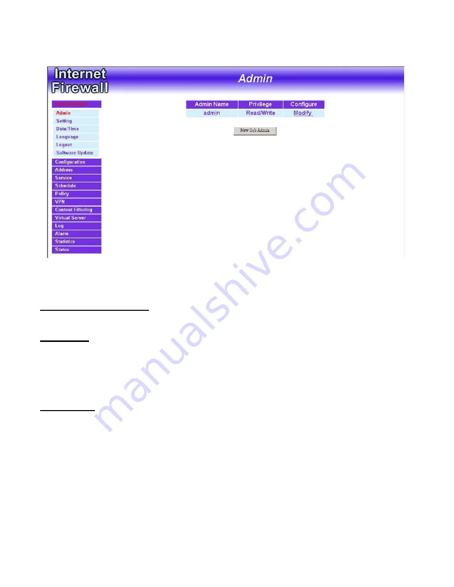
Administration

, and then select 

Administrator 

below it. The current list of Administrator(s) shows up.


Settings of the Administration table: 
 

Administrator Name:

 The username of Administrators for the firewall.  The 

user 

admin

 cannot be removed.   

Privilege:

 The privileges of Administrators (Admin or Sub Admin)   

The username of the main Administrator is 

Administrator

 with 

read/write


privilege. 
Sub Admins may be created by the 

Admin

 by clicking 

New Sub Admin.  


Sub Admins have 

read only

 privilege. 

Configure:

 Click 

Modify

 to change the “Sub Administrator’s” password and 

click 

Remove

 to delete a “Sub Administrator.”


- 6 - 


Содержание DFL-300 - Security Appliance

Страница 1: ... 1 FIREWALL VPN ROUTER User s Manual Doc No 120602 01 ...

Страница 2: ...ing 10 Date Time 16 Language 17 Logout 18 Software Update 19 Configuration 20 Interface 21 Multiple NAT 25 Hack Alert 32 Route Table 33 DHCP 37 DNS Proxy 39 Dynamic DNS 44 Address 49 Interface 50 Internal Group 54 External 58 External Group 62 ...

Страница 3: ...Group 80 Schedule 84 Policy 88 Outgoing 89 Incoming 97 External To DMZ Internal to DMZ 103 DMZ To External DMZ To Internal 109 VPN 115 Autokey IKE 116 PPTP Server 120 PPTP Client 126 Content filtering 130 URL Blocking 131 General Blocking 135 Virtual Server 136 ...

Страница 4: ...38 Virtual Server 142 LOG 150 Traffic Log 151 Event Log 154 Log Report 157 Alarm 160 Traffic Alarm 161 Event Alarm 164 Statistics 167 Status 168 Interface Status 168 ARP Table 169 DHCP Clients 170 Setup Examples 171 ...

Страница 5: ... under Administrator are Administrator Setting and Software Update Administrator has control of user access to the firewall He she can add remove users and change passwords Setting The Administrator may use this function to backup firewall configurations and export save them to an Administrator computer or anywhere on the network or restore a configuration file to the FIREWALL VPN ROUTER or restor...

Страница 6: ...e of Administrators for the firewall The user admin cannot be removed Privilege The privileges of Administrators Admin or Sub Admin The username of the main Administrator is Administrator with read write privilege Sub Admins may be created by the Admin by clicking New Sub Admin Sub Admins have read only privilege Configure Click Modify to change the Sub Administrator s password and click Remove to...

Страница 7: ...on to create a new Sub Administrator Step 2 In the Add New Sub Administrator window Sub Admin Name enter the username of new Sub Admin Password enter a password for the new Sub Admin Confirm Password enter the password again Step 3 Click OK to add the user or click Cancel to cancel the addition 7 ...

Страница 8: ...it and click on Modify in the Configure field Step 2 The Modify Administrator Password window will appear Enter in the required information Password enter original password New Password enter new password Confirm Password enter the new password again Step 3 Click OK to confirm password change or click Cancel to cancel it 8 ...

Страница 9: ...Administration table locate the Administrator name you want to edit and click on the Remove option in the Configure field Step 2 The Remove confirmation pop up box will appear Step 3 Click OK to remove that Sub Admin or click Cancel to cancel 9 ...

Страница 10: ...ttings window Click Setting in the Administrator menu to enter the Settings window The Firewall Configuration settings will be shown on the screen Exporting FIREWALL VPN ROUTER Firewall settings Step 1 Under Firewall Configuration click on the Download button next to Export System Settings to Client Step 2 When the File Download pop up window appears choose the destination place in which to save t...

Страница 11: ...lick on the Browse button next to Import System Settings When the Choose File pop up window appears select the file to which contains the saved Firewall Settings then click OK Step 2 Click OK to import the file into the Firewall or click Cancel to cancel importing 11 ...

Страница 12: ...Restoring Factory Default Settings Step 1 Select Reset Factory Settings under Firewall Configuration Step 2 Click OK at the bottom right of the screen to restore the factory settings 12 ...

Страница 13: ... network is being attacked by hackers or when emergency conditions occur Step 2 SMTP Server IP Enter SMTP server s IP address Step 3 E Mail Address 1 Enter the first e mail address to receive the alarm notification Step 4 E Mail Address 2 Enter the second e mail address to receive the alarm notification Optional Step 5 Click OK on the bottom right of the screen to enable E mail alert notification ...

Страница 14: ...o Firewall Packets Log Select this option to the FIREWALL VPN ROUTER s To Firewall Packets Log Once this function is enabled every packet to this appliance will be recorded for system manager to trace 14 ...

Страница 15: ...enabled the firewall will be rebooted Step 1 Click Setting in the Administration menu to enter the settings window Step 2 Reboot Firewall Click Reboot Step 3 A confirmation pop up box will appear Step 4 Follow the confirmation pop up box click OK to restart firewall or click Cancel to discard changes 15 ...

Страница 16: ...e system clock every minutes You can set the interval time to synchronize with outside servers If you set it to 0 it means the device will not synchronize automatically Step 5 Synchronize system clock with this client You can synchronize this Homing Gateway with this client computer by clicking the Sync button Step 6 Click the OK button below to change the setting or click Cancel to discard change...

Страница 17: ...ese Version and English version for you to choose Step 1 Click Language Step 2 Select the language version you want Traditional Chinese Version Simplified Chinese Version and English version Step 3 Click OK to change the language version or click Cancel to discard changes 17 ...

Страница 18: ...Select this option to the FIREWALL VPN ROUTER s Logout the firewall this function protects your system while you are away Step 1 Click Logout the firewall Step 2 Click OK to logout or click Cancel to discard the change 18 ...

Страница 19: ...Software Update Under Software Update the admin may update the FIREWALL VPN ROUTER s software with a newer software 19 ...

Страница 20: ... Set up the Firewall detecting functions 4 Set up a static route 5 Set up the DHCP Server 6 Set up DNS Proxy 7 Set up Dynamic DNS Note After all the settings of the Firewall configuration have been set the Administrator can backup the System configuration into the local hard drive as shown in the Administrator section of this manual under the heading 1 2 Settings ...

Страница 21: ...erface below it The current settings of the interface addresses will appear on the screen Configuring the Interface Settings Internal Interface Using the Internal Interface the Administrator sets up the Internal LAN network The Internal network will use a private IP scheme The private IP network will not be routable on the Internet IP Address The private IP address of the Firewall s internal netwo...

Страница 22: ...he External WAN network These IP Addresses are real public IP Addresses and are routable on the Internet For PPPoE ADSL User This option is for PPPoE users who are required to enter a username and password in order to connect such as ADSL users Current Status Displays the current line status of the PPPoE connection IP Address Displays the IP Address of the PPPoE connection Username Enter the PPPoE...

Страница 23: ...our ISP you do not have to enter a hostname Ping Select this to allow the external network to ping the IP Address of the Firewall This will allow people from the Internet to be able to ping the Firewall If set to enable the FIREWALL VPN ROUTER will respond to echo request packets from the external network WebUI Select this to allow the FIREWALL VPN ROUTER WEBUI to be accessed from the External WAN...

Страница 24: ... The Administrator uses the DMZ Interface to set up the DMZ network The DMZ network consists of server computers such as FTP SMTP and HTTP web These server computers are put in the DMZ network so they can be isolated from the Internal LAN network traffic Broadcast messages from the Internal network will not cross over to the DMZ network to cause congestions and slow down these servers This allows ...

Страница 25: ...2 Service department subnetwork 192 168 2 11 24 Internal 168 85 88 252 External 3 Sales department subnetwork 192 168 3 11 24 Internal 168 85 88 251 External 4 Procurement department subnetwork 192 168 4 11 24 Internal 168 85 88 250 External 5 Accounting department subnetwork 192 168 5 11 24 Internal 168 85 88 249 External The first department R D department was set while setting interface IP the ...

Страница 26: ... NAT window Multiple NAT Global port interface IP Address Global port IP Address Local port interface IP Address Local port IP Address and subnet Mask Modify Modify the settings of Multiple NAT Click Modify to modify the parameters of Multiple NAT or click Delete to delete settings 26 ...

Страница 27: ...o add Multiple NAT Step 3 Enter the IP Address in the website name column of the new window 1 1 Global port interface IP Address Select Global port IP Address 3 2 Local port interface IP Address Enter Local port IP Address 3 3 Subnet Mask Enter Local port subnet Mask Step 4 Click OK to add Multiple NAT or click Cancel to discard changes ...

Страница 28: ...guration menu to enter Multiple NAT window Step 2 Find the IP Address you want to modify and click Modify Step 3 Enter the new IP Address in Modify Multiple NAT window Step 4 Click the OK button below to change the setting or click Cancel to discard changes 28 ...

Страница 29: ...iple NAT in the Configuration menu to enter Multiple NAT window Step 2 Find the IP Address you want to delete and click Delete Step 3 A confirmaion pop up box will appear click OK to delete the setting or click Cancel to discard changes 29 ...

Страница 30: ...ng to the servers After enabling this function the System Administrator can enter the number of SYN packets per second that is allow to enter the network firewall Once the SYN packets exceed this limit the activity will be logged in Alarm and an email alert is sent to the Administrator The default SYN flood threshold is set to 200 Pkts Sec Detect ICMP Flood Select this option to detect ICMP flood ...

Страница 31: ... make it necessary to restart the computer to get a normal operation Detect Tear Drop Attack Select this option to detect tear drop attacks These are packets that are segmented to small packets with negative length Some Systems treat the negative value as a very large number and copy enormous data into the System to cause System damage such as a shut down or a restart Detect IP Spoofing Attack Sel...

Страница 32: ...rce port and destination port and when SYN on the TCP header is marked Enable this function to detect such abnormal packets Default Packet Deny Denies all packets from passing the Firewall A packet can pass only when there is a policy that allows it to pass After enabling the needed detect functions click OK to activate the changes ...

Страница 33: ...k Route Table below it The Route Table window appears in which current route settings are shown Route Table functions Interface Destination network internal or external networks Destination IP IP address of destination network NetMask Netmask of destination network Gateway Gateway IP address for connecting to destination network Configure Change settings in the route table 33 ...

Страница 34: ... New Entry button Step 2 In the Add New Static Route window enter new static route information Step 3 In the Interface field s pull down menu choose the network to connect Internal External or DMZ Step 4 Click OK to add the new static route or click Cancel to cancel 34 ...

Страница 35: ...e Table menu find the route to edit and click the corresponding Modify option in the Configure field Step 2 In the Modify Static Route window modify the necessary routing addresses Step 3 Click OK to apply changes or click Cancel to cancel it 35 ...

Страница 36: ...tep 1 In the Route Table window find the route to remove and click the corresponding Remove option in the Configure field Step 2 In the Remove confirmation pop up box click OK to confirm removing or click Cancel to cancel it 36 ...

Страница 37: ...ep 1 Click Configuration on the left hand side menu bar and then click DHCP below it The DHCP window appears in which current DHCP settings are shown on the screen Dynamic IP Address functions Subnet Internal network s subnet NetMask Internal network s netmask Gateway Internal network s gateway IP address Broadcast Internal network s broadcast IP address 37 ...

Страница 38: ...red Step 3 Domain Name Server Enter in the IP address of the DNS Server to be assigned to the Internal network Step 4 Client IP Address Range 1 Enter the starting and the ending IP address dynamically assigning to DHCP clients Step 5 Client IP Address Range 2 Enter the starting and the ending IP address dynamically assigning to DHCP clients Optional Step 6 Click OK to enable DHCP support ...

Страница 39: ...l DNS server will assign them a public IP address for the mail server So for the Internal network to access the mail server mail dfl300 com they would have to go out to the Internet then come back through the Firewall to access the mail server Essentially the internal network is accessing the mail server by a real public IP address while the mail server serves their request by a NAT address and no...

Страница 40: ...lick on DNS Proxy below it The DNS Proxy window will appear Below is the information needed for setting up the DNS Proxy Domain Name The domain name of the server Virtual IP Address The virtual IP address respective to DNS Proxy Configure modify or remove each DNS Proxy policy 40 ...

Страница 41: ... Step 1 Click on the New Entry button and the Add New DNS Proxy window will appear Step 2 Fill in the appropriate settings for the domain name and virtual IP address Step 3 Click OK to save the policy or Cancel to cancel 41 ...

Страница 42: ...he DNS Proxy window find the policy to be modified and click the corresponding Modify option in the Configure field Step 2 Make the necessary changes needed Step 3 Click OK to save changes or click on Cancel to cancel modifications 42 ...

Страница 43: ...Step 1 In the DNS Proxy window find the policy to be removed and click the corresponding Remove option in the Configure field Step 2 A confirmation pop up box will appear click OK to remove the DNS Proxy or click Cancel 43 ...

Страница 44: ...e fail Unidentified error Domain name Enter the password provided by ISP WAN IP Address IP Address of the WAN port Modify Modify dynamic DNS settings Click Modify to change the DNS parameters click Delete to delete the settings 2 How to use dynamic DNS The firewall provides 3 service providers users have to register first to use this function For the usage regulations see the providers websites Ho...

Страница 45: ... 45 ...

Страница 46: ...ervice providers Register to the service providers website WAN IP Address IP Address of the WAN port automatically fill in the external IP Check to automatically fill in the external IP User Name Enter the registered user name Password Enter the password provided by ISP Internet Service Provider Domain name Your host domain name provided by ISP Step 4 Click OK to add dynamic DNS or click Cancel to...

Страница 47: ...he Configuration menu to enter Dynamic DNS window Step 2 Find the item you want to change and click Modify Step 3 Enter the new information in the Modify Dynamic DNS window Step 4 Click OK to change the settings or click Cancel to discard changes 47 ...

Страница 48: ...namic DNS in the Configuration menu to enter Dynamic DNS window Step 2 Find the item you want to change and click Delete Step 3 A confirmation pop up box will appear click OK to delete the settings or click Cancel to discard changes 48 ...

Страница 49: ...he Administrator needs to create a control policy for packets of different IP addresses he can first add a new group in the Internal Network Group or the External Network Group and assign those IP addresses into the newly created group Using group addresses can greatly simplify the process of building control policies With easily recognized names of IP addresses and names of address groups shown i...

Страница 50: ... the Internal window Step 1 Click Internal under the Address menu to enter the Internal window The current setting information such as the name of the internal network IP and Netmask addresses will show on the screen 50 ...

Страница 51: ...1 In the Internal window click the New Entry button Step 2 In the Add New Address window enter the settings of a new internal network address Step 3 Click OK to add the specified internal network or click Cancel to cancel the changes 51 ...

Страница 52: ... the network to be modified Click the Modify option in its corresponding Configure field The Modify Address window appears on the screen immediately Step 2 In the Modify Address window fill in the new addresses Step 3 Click OK to save changes or click Cancel to discard changes 52 ...

Страница 53: ... the Internal window locate the name of the network to be removed Click the Remove option in its corresponding Configure field Step 2 In the Remove confirmation pop up box click OK to remove the address or click Cancel to discard changes 53 ...

Страница 54: ...up window The Internal Addresses may be combined together to become a group Click Internal Group under the Address menu to enter the Internal Group window The current setting information for the Internal network group appears on the screen 54 ...

Страница 55: ...ist the names to be assigned to the new group Name enter the name of the new group in the open field Step 3 Add members Select names to be added in Available Address list and click the Add button to add them to the Selected Address list Step 4 Remove members Select names to be removed in the Selected Address list and click the Remove button to remove these members from Selected Address list Step 5...

Страница 56: ... list names of all members of the Internal network Selected Address list names of members which have been assigned to this group Step 3 Add members Select names in Available Address list and click the Add button to add them to the Selected Address list Step 4 Remove members Select names in the Selected Address list and click the Remove button to remove these members from the Selected Address list ...

Страница 57: ...In the Internal Group window locate the group to be removed and click its corresponding Remove option in the Configure field Step 2 In the Remove confirmation pop up box click OK to remove the group or click Cancel to discard changes 57 ...

Страница 58: ...ing the External window Click External under the Address menu to enter the External window The current setting information such as the name of the External network IP and Netmask addresses will show on the screen 58 ...

Страница 59: ... 1 In the External window click the New Entry button Step 2 In the Add New Address window enter the settings for a new external network address Step 3 Click OK to add the specified external network or click Cancel to discard changes 59 ...

Страница 60: ...e network to be modified and click the Modify option in its corresponding Configure field Step 2 The Modify Address window will appear on the screen immediately In the Modify Address window fill in new addresses Step 3 Click OK to save changes or click Cancel to discard changes 60 ...

Страница 61: ...he External table locate the name of the network to be removed and click the Remove option in its corresponding Configure field Step 2 In the Remove confirmation pop up box click OK to remove the address or click Cancel to discard changes 61 ...

Страница 62: ...al Group Entering the External Group window Click the External Group under the Address menu bar to enter the External window The current settings for the external network group s will appear on the screen 62 ...

Страница 63: ...mes of all the members of the external network Selected Address List the names to assign to the new group Step 3 Add members Select the names to be added in the Available Address list and click the Add button to add them to the Selected Address list Step 4 Remove members Select the names to be removed in the Selected Address list and click the Remove button to remove them from the Selected Address...

Страница 64: ...members of the external network Selected Address list the names of the members that have been assigned to this group Step 3 Add members Select the names to be added in the Available Address list and click the Add button to add them to the Selected Address list Step 4 Remove members Select the names to be removed in the Selected Address list and click the Remove button to remove them from the Selec...

Страница 65: ...In the External Group window locate the group to be removed and click its corresponding Modify option in the Configure field Step 2 In the Remove confirmation pop up box click OK to remove the group or click Cancel to discard changes 65 ...

Страница 66: ...Entering the DMZ window Click DMZ under the Address menu to enter the DMZ window The current setting information such as the name of the internal network IP and Netmask addresses will show on the screen 66 ...

Страница 67: ... Address Step 1 In the DMZ window click the New Entry button Step 2 In the Add New Address window enter the settings for a new DMZ address Step 3 Click OK to add the specified DMZ or click Cancel to discard changes 67 ...

Страница 68: ...dow locate the name of the network to be modified and click the Modify option in its corresponding Configure field Step 2 In the Modify Address window fill in new addresses Step 3 Click OK on save the changes or click Cancel to discard changes 68 ...

Страница 69: ...e DMZ window locate the name of the network to be removed and click the Remove option in its corresponding Configure field Step 2 In the Remove confirmation pop up box click OK to remove the address or click Cancel to discard changes 69 ...

Страница 70: ...DMZ Group Entering the DMZ Group window Click DMZ Group under the Address menu to enter the DMZ window The current settings information for the DMZ group appears on the screen 70 ...

Страница 71: ...group Step 3 Name enter a name for the new group Step 4 Add members Select the names to be added from the Available Address list and click the Add button to add them to the Selected Address list Step 5 Remove members Select names to be removed from the Selected Address list and click the Remove button to remove them from the Selected Address list Step 6 Click OK to add the new group or click Cance...

Страница 72: ...the members of the DMZ Selected Address list the names of the members that have been assigned to this group Step 3 Add members Select names to be added from the Available Address list and click the Add button to add them to the Selected Address list Step 4 Remove members Select names to be removed from the Selected Address list and click the Remove button to remove them from Selected Address list ...

Страница 73: ...DMZ Group Step 1 In the DMZ Group window locate the group to be removed and click its corresponding Remove option in the Configure field Step 2 In the Remove confirmation pop up box click OK to remove the group 73 ...

Страница 74: ...ed service and cannot be modified or removed In the custom menu users can define other TCP port and UDP port numbers that are not in the pre defined menu according to their needs When defining custom services the client port ranges from 1024 to 65535 and the server port ranges from 0 to 1023 How do I use Service The Administrator can add new service group names in the Group option under Service me...

Страница 75: ...g a Pre defined window Click Service on the menu bar on the left side of the window Click Pre defined under it A window will appear with a list of services and their associated IP addresses This list cannot be modified 75 ...

Страница 76: ... Entering the Custom window Click Service on the menu bar on the left side of the window Click Custom under it A window will appear with a table showing all services currently defined by the Administrator 76 ...

Страница 77: ...ew service Protocol Enter the network protocol type to be used such as TCP UDP or Other please enter the number for the protocol type Client Port enter the range of port number of new clients Server Port enter the range of port number of new servers The client port ranges from 1024 to 65535 and the server port ranges from 0 to 1023 Step 3 Click OK to add new services or click Cancel to cancel 77 ...

Страница 78: ...name of the service to be modified Click its corresponding Modify option in the Configure field Step 2 A table showing the current settings of the selected service appears on the screen Step 3 Enter the new values Step 4 Click OK to accept editing or click Cancel 78 ...

Страница 79: ...n the Custom window locate the service to be removed Click its corresponding Remove option in the Configure field Step 2 In the Remove confirmation pop up box click OK to remove the selected service or click Cancel to cancel action 79 ...

Страница 80: ...sing the Group window Click Service in the menu bar on the left hand side of the window Click Group under it A window will appear with a table displaying current service group settings set by the Administrator 80 ...

Страница 81: ...p Step 2 Enter the new group name in the group Name field This will be the name referencing the created group Step 4 To add new services Select the services desired to be added in the Available Services list and then click the Add button to add them to the group Step 5 To remove services Select services desired to be removed in the Available Services and then click the Remove button to remove them...

Страница 82: ...ces lists all the available services Selected Services list services that have been assigned to the selected group Step 3 Add new services Select services in the Available Services list and then click the Add button to add them to the group Step 4 Remove services Select services to be removed in the Selected Services list and then click the Remove button to remove theses services from the group St...

Страница 83: ...up window locate the service group to be removed and click its corresponding Remove option in the Configure field Step 2 In the Remove confirmation pop up box click OK to remove the selected service group or click Cancel to cancel removing 83 ...

Страница 84: ... as well as creating 2 different time periods in a day For example an organization may only want the Firewall to allow the internal network users to access the Internet during work hours Therefore the Administrator may create a schedule to allow the Firewall to work Monday Friday 8AM 5PM only During the non work hours the Firewall will not allow Internet access Accessing the Schedule window Click ...

Страница 85: ...chedule window will appear Step 2 Schedule Name Fill in a name for the new schedule Period 1 Configure the start and stop time for the days of the week that the schedule will be active Step 3 Click Ok to save the new schedule or click Cancel to cancel adding the new schedule 85 ...

Страница 86: ...ifying a Schedule Step 1 In the Schedule window find the policy to be modified and click the corresponding Modify option in the Configure field Step 2 Make needed changes Step 3 Click OK to save changes 86 ...

Страница 87: ...hedule Step 1 In the Schedule window find the policy to be removed and click the corresponding Remove option in the Configure field Step 2 A confirmation pop up box will appear click on OK to remove the schedule 87 ...

Страница 88: ... server is in DMZ 4 From DMZ a client is in DMZ while server is either in the internal networks or in the external networks How do I use Policy 88 The policy settings are source addresses destination addresses services permission log statistics and flow alarm Among them source addresses destination addresses and IP mapping addresses have to be defined in the Address menu in advance Services can be...

Страница 89: ...ork addresses that are specified in the Internal section of Address menu or all the Internal LAN network addresses Destination destination network addresses that are specified in the External section of the Address menu or all the External WAN network addresses Service specify services provided by external network servers Action control actions to permit or reject deny packets from internal networ...

Страница 90: ...the Address menu To create a new source address please go to the Internal section under the Address menu Destination Address Select the name of the External WAN network from the drop down list The drop down list contains the names of all external networks defined in the External section of the Address window To create a new destination address please go to the External section under the Address me...

Страница 91: ...ination network Logging Select Enable to enable flow monitoring Statistics Select Enable to enable flow statistics Alarm Threshold set a maximum flow rate in Kbytes Sec An alarm will be sent if flow rates are higher than the specified value Step 3 Click OK to add a new outgoing policy or click Cancel to cancel adding a new outgoing policy ...

Страница 92: ...In the Modify Policy window fill in new settings Note To change or add selections in the drop down list for source or destination address go to the section where the selections are setup Source Address Internal of Address menu Destination Address External of Address menu Service Pre defined Custom or Group under Service Step 3 Click OK to do confirm modification or click Cancel to cancel it 92 ...

Страница 93: ...ing policy section locate the name of the policy desired to be removed and click its corresponding Remove option in the Configure field Step 2 In the Remove confirmation dialogue box click OK to remove the policy or click Cancel to cancel removing 93 ...

Страница 94: ...affic and event passing through the Firewall The Administrator can click Log on the left menu bar to get the flow and event logs of the specified policy Note System Administrator can back up and clear logs in this window Check the chapter entitled Log to get details about the log and ways to back up and clear logs 94 ...

Страница 95: ...event alarms passing through the Firewall The Administrator can click Alarm on the left menu to get the logs of flow and event alarms of the specified policy Note The Administrator can also get information on alarm logs from the Alarm window Please refer to the section entitled Alarm for more information 95 ...

Страница 96: ... in the outgoing policy the FIREWALL VPN ROUTER will display the flow statistics passing through the Firewall Note The Administrator can also get flow statistics in Statistics Please refer to Statistics in Chapter 11 for more details 96 ...

Страница 97: ... network to assigned Mapped IP or Virtual Server Step 2 The fields of the Incoming window are Source source networks which are specified in the External section of the Address menu or all the external network addresses Destination destination networks which are IP Mapping addresses or Virtual server network addresses created in Virtual Server menu Service services supported by Virtual Servers or M...

Страница 98: ...functions on packets from external networks to Virtual Server Mapped IP travelling through the Firewall Configure modify settings or remove incoming policy Move this sets the priority of the policies number 1 being the highest priority ...

Страница 99: ...ed in the Mapped IP or the Virtual Server sections of Virtual Server menu To create a new destination address please go to the Virtual Server menu Please refer to Chapter 8 for Virtual Server for details Service Specified services provided by internal network servers These are services application that are allowed to pass from the External network to the Internal network Choose ANY for all service...

Страница 100: ... 100 be sent if flow rates are higher than the specified value Step 3 Click OK to add new policy or click Cancel to cancel adding new incoming policy ...

Страница 101: ...ow locate the name of policy desired to be modified and click its corresponding Modify option in the Configure field Step 2 In the Modify Policy window fill in new settings Step 3 Click OK to save modifications or click Cancel to cancel modifications 101 ...

Страница 102: ...n the Incoming window locate the name of policy desired to be removed and click its corresponding Remove in the Configure field Step 2 In the Remove confirmation window click Ok to remove the policy or click Cancel to cancel removing 102 ...

Страница 103: ...der Policy menu to enter the External To DMZ window The External To DMZ table will show up displaying currently defined policies The fields in External To DMZ window Source source networks which are addresses specified in the External section of the Address menu or all the external network addresses Destination destination networks which are addresses specified in DMZ section of the Address menu a...

Страница 104: ...ny packets from external networks to DMZ travelling through the FIREWALL VPN ROUTER Option specify the monitoring functions of packets from external network to DMZ network travelling through Firewall Configure modify settings or remove policies ...

Страница 105: ...t contains the names of the DMZ network created in the Address menu It will also contain Mapped IP addresses from the Virtual Server menu that were created for the DMZ network To create a new destination address please go to the Virtual Server menu Please refer to the sections entitled Address and Virtual Server for details Service Select a service from drop down list The drop down list will conta...

Страница 106: ...he packets travelling from the specified external network to the DMZ network Logging select Enable to enable flow monitoring Statistics select Enable to enable flow statistics Alarm Threshold set a maximum flow rate in Kbytes Sec An alarm will be send if a flow rate exceeds the specified value Step 3 Click OK ...

Страница 107: ...In the External To DMZ window locate the name of policy desired to be modified and click its corresponding Modify option in the Configure field Step 2 In the Modify Policy window fill in new settings Step 3 Click OK to do save modifications 107 ...

Страница 108: ...icy Step 1 In the External To DMZ window locate the name of policy desired to be removed and click its corresponding Remove option in the Configure field Step 2 In the Remove confirmation pop up box click OK to remove the policy 108 ...

Страница 109: ... menu and the DMZ To External table appears displaying currently defined DMZ To External policies The fields in the DMZ To External window are Source source network addresses which are specified in the DMZ section of the Address window Destination destination networks which is the external network address Service services supported by Servers of external networks Action control actions to permit o...

Страница 110: ... monitoring functions on packets from the DMZ network to external networks travelling through the Firewall Configure modify settings or remove policies Move this sets the priority of the policies number 1 being the highest priority ...

Страница 111: ...ss Select the name of the external network from the drop down list The drop down list lists names of addresses defined in External section of the Address menu To add a new destination address please go to External section of the Address menu Service Select a service from drop down list The drop down list will contain services defined in the Custom or Group section under the Service menu These are ...

Страница 112: ...DMZ network to the external network Logging select Enable to enable flow monitoring Statistics click Enable to enable flow statistics Alarm Threshold set a maximum flow rate in Kbytes Sec An alarm will be sent if the flow rate exceeds the specified value Step 3 Click OK to add new policy or click Cancel to cancel adding ...

Страница 113: ...onfigure field Step 2 In the Modify Policy window fill in new settings Note To change or add selections in the drop down list go to the section where the selections are setup Source Address DMZ of Address Destination Address External Service Pre defined Service Custom or Group under Service Step 3 Click OK to save modifications or click Cancel to cancel modifications 113 ...

Страница 114: ...ernal Policy Step 1 In the DMZ To External window locate the name of policy desired to be removed and click its corresponding Remove option in the Configure field Step 2 In the Remove confirmation dialogue box click OK 114 ...

Страница 115: ... VPN To set up a Virtual Private Network VPN you don t need to configure an Access Policy to enable encryption Just fill in the following settings VPN Name Source Subnet Destination Gateway Destination Subnet Authentication Method Preshare key Encapsulation and IPSec lifetime The firewalls on both ends must use the same Preshare key and IPSec lifetime to make a VPN connection ...

Страница 116: ...lick Autokey IKE under the VPN menu to enter the Autokey IKE window The Autokey IKE table displays current configured VPNs The fields in the Autokey IKE window are Name The VPN name to identify the VPN tunnel definition The name must be different for the two sites creating the tunnel Gateway IP The external interface IP address of the remote Firewall Destination Subnet Destination network subnet P...

Страница 117: ... used to provide authentication The IP Encapsulating Security Header ESP is used to provide confidentially to IP datagrams ESP Encryption Algorithm The FIREWALL VPN ROUTER auto selects 56 bit DES CBC or 168 bit Triple DES CBC encryption algorithm The default algorithm is 168 bit Triple DES CBC ESP Authentication Method The FIREWALL VPN ROUTER auto selects MD5 or SHA 1 authentication algorithm The ...

Страница 118: ... Modify Policy window fill in new settings Step 3 Click OK to save modifications Connecting the VPN connection Once all the policy is created with the correct settings click on the Connect option in the Configure field The Status field will change to indicate Connecting If the remote Firewall is set up correctly with the VPN active the VPN connection will be made between the two Firewalls and the ...

Страница 119: ...e the name of the Autokey IKE desired to be removed and click its corresponding Delete option in the Configure field Step 2 In the Remove confirmation pop up box click OK to remove the Autokey IKE or click Cancel to cancel deleting 119 ...

Страница 120: ...for PPTP Client connection User Name Displays the PPTP Client user s name for authentication Client IP Displays the PPTP Client s IP address for authentication Uptime Displays the connection time between PPTP Server and Client Status Displays current connection status between PPTP Server and PPTP client Configure Click Modify to modify the PPTP Client settings or click Remove to remove the item ...

Страница 121: ...Client IP Range Enter the IP range allocated for PPTP Client to connect to the PPTP server Auto Disconnect if idle minutes Configure this device to disconnect to the PPTP Server when there is no activity for a predetermined period of time To keep the line always connected set the number to 0 Schedule Click the down arrow to select the schedule which was pre determined in Schedule Refer to the corr...

Страница 122: ...TP client password Remote Client Single Machine Check to connect to single computer Multi Machine Check to allow multiple computers connected to the PPTP server IP Address Enter the PPTP Client IP address Netmask Enter the PPTP Client Sub net mask Client IP assigned by 1 IP Range check to enable auto allocating IP for PPTP client to connect 2 Fixed IP check and enter a fixed IP for PPTP client to ...

Страница 123: ...Step 3 Click OK to save modifications or click Cancel to cancel modifications 123 ...

Страница 124: ...t VPN PPTP Server Step 2 Step 3 In the PPTP Server window find the PPTP server that you want to modify Click Configure and click Modify Enter appropriate settings Step 4 Click OK to save modifications or click Cancel to cancel modifications ...

Страница 125: ...5 Step 1 Step 2 Step 3 Select VPN PPTP Server In the PPTP Server window find the PPTP server that you want to modify Click Configure and click remove Click OK to remove the PPTP server or click Cancel to exit without removal ...

Страница 126: ...the PPTP Client user s name for authentication Client IP Displays the PPTP Client s IP address for authentication Uptime Displays the connection time between PPTP Server and Client Status Displays current connection status between PPTP Server and PPTP client Configure Click Modify to modify the PPTP Client settings or click Remove to remove the item ...

Страница 127: ...sk Enter the PPTP Client Sub net mask Auto Connect when sending packet through the link Check to enable the auto connection whenever there s packet to transmit over the connection Auto Disconnect if idle minutes Configure this device to disconnect to the PPTP Server when there is no activity for a predetermined period of time To keep the line always connected set the number to 0 Schedule Click the...

Страница 128: ...t VPN PPTP Client Step 2 Step 3 In the PPTP Client window find the PPTP server that you want to modify Click Configure and click Modify Enter appropriate settings Step 4 Click OK to save modifications or click Cancel to cancel modifications ...

Страница 129: ...9 Step 1 Step 2 Step 3 Select VPN PPTP Client In the PPTP Client window find the PPTP client that you want to modify Click Configure and click remove Click OK to remove the PPTP client or click Cancel to exit without removal ...

Страница 130: ...nd general filtering Content Filtering includes URL Blocking and General Blocking 一 URL Blocking The device manager can use a complete domain name key word or to make rules for specific websites 二 General Blocking To let Popup ActiveX Java Cookie in or keep them out ...

Страница 131: ...rom accessing a specific website on the Internet Any web request coming from an Internal network computer to a blocked website will receive a blocked message instead of the website Entering the URL blocking window Click on URL Blocking under the Configuration menu bar Click on New Entry 131 ...

Страница 132: ...L Blocking policy Step 1 After clicking New Entry the Add New Block String window will appear Step 2 Enter the URL of the website to be blocked Step 3 Click OK to add the policy Click Cancel to discard changes 132 ...

Страница 133: ... the URL Blocking window find the policy to be modified and click the corresponding Modify option in the Configure field Step 2 Make the necessary changes needed Step 3 Click on OK to save changes or click on Cancel to cancel modifications 133 ...

Страница 134: ...and click the corresponding Remove option in the Configure field Step 2 A confirmation pop up box will appear click on OK to remove the policy or click on Cancel to discard changes Blocked URL site When a user from the Internal network tries to access a blocked URL the error below will appear 134 ...

Страница 135: ...king detective functions Popup filtering Prevent the pop up boxes appearing ActiveX filtering Prevent ActiveX packets Java filtering Prevent Java packets Cookie filtering Prevent Cookie packets Step 3 After selecting each function click the OK button below When the system detects the setting the firewall will spontaneously work 135 ...

Страница 136: ...one to many mapping This is when one virtual server IP address on the external interface can be mapped into 4 internal network server private IP addresses This option is useful for Load Balancing which causes the virtual server to distribute data packets to each private IP addresses which are the real servers By sending all data packets to all similar servers this increases the server s efficiency...

Страница 137: ...vate internal IP address of the physical server that supports the services Therefore users from the external network can access servers of the internal network by requesting the service from the IP address provided by Virtual Server ...

Страница 138: ...rs have to first connect to a real IP address of the external network and the real IP is translated to a private IP of the internal network Mapped IP and Virtual Server are the two methods to translate the real IP into private IP Mapped IP maps IP in one to one fashion that means all services of one real external IP address is mapped to one private internal IP address Entering the Mapped IP window...

Страница 139: ...ew Mapped IP window will appear External IP select the external public IP address to be mapped Internal IP enter the internal private IP address or DMZ IP address which will be mapped 1 to 1 to the external IP address Step 2 Click OK to add new IP Mapping or click Cancel to cancel adding 139 ...

Страница 140: ...d and click its corresponding Modify option in the Configure field Step 2 Enter settings in the Modify Mapped IP window Step 3 Click OK to save change or click Cancel to cancel Note A Mapped IP cannot be modified if it has been assigned used as a destination address of any Incoming policies 140 ...

Страница 141: ... Mapped IP table locate the Mapped IP desired to be removed and click its corresponding Remove option in the Configure field Step 2 In the Remove confirmation pop up window click Ok to remove the Mapped IP or click Cancel to cancel 141 ...

Страница 142: ...e external interface to private IP addresses of the internal network This is done to provide services or applications defined in the Service menu to enter into the internal network Unlike a mapped IP which binds an external IP to an Internal DMZ IP virtual server binds external IP ports to Internal IP ports ...

Страница 143: ...k here to configure button and the Add new Virtual Server IP window appears and asks for an IP address from the external network Step 3 Select an IP address from the drop down list of available external network IP addresses Note If the drop down list contains only Disable there is no available IP addresses of external network of the System and no Virtual Server can be added Step 4 Click OK to add ...

Страница 144: ...When Disable appears in the drop down list no Virtual Server can be added 144 ...

Страница 145: ...rver menu bar A new window appears displaying the IP address and service of the specified virtual server Step 2 Click on the Virtual Server s IP Address button at the top of the screen Step 3 Choose a new IP address from the drop down list Step 4 Click OK to save new IP address or click Cancel to cancel modification 145 ...

Страница 146: ...er option under the Virtual Server menu bar A new window displaying the virtual server s IP address and service appears on the screen Step 2 Click the Virtual Server s IP Address button at the top of the screen Step 3 Select Disable in the drop down list in Step 4 Click OK to remove the virtual server 146 ...

Страница 147: ...umber that the virtual server will use Changing the Service will change the port number to match the service Service select the service from the pull down list that will be provided by the Virtual Server Note The services in the drop down list are all defined in the Pre defined and Custom section of the Service menu Step 3 Enter the IP address of the internal network server s to which the virtual ...

Страница 148: ...ed and click its corresponding Modify option in the Configure field Step 2 In the Virtual Server Configuration window enter the new settings Step 3 Click OK to save modifications or click Cancel to cancel modification Note A virtual server cannot be modified or removed if it has been assigned to the destination address of any Incoming policies 148 ...

Страница 149: ...erver window s service table locate the name of the service desired to be removed and click its corresponding Remove option in the Configure field Step 2 In the Remove confirmation pop up box click Ok to remove the service or click Cancel to cancel removing 149 ...

Страница 150: ...ters are setup when setting up control policies Traffic logs record the details of packets such as the start and stop time of connection the duration of connection the source address the destination address and services requested for each control policy Event logs record the contents of System Configuration changes made by the Administrator such as the time of change settings that change the IP ad...

Страница 151: ...tion under Log menu to enter the Traffic Log window Traffic Log The table in the Traffic Log window displays current System statuses Time The start time of the connection Source IP address of the source network of the specific connection Destination IP address of the destination network of the specific connection Protocol Port Protocol type and Port number of the specific connection Disposition Ac...

Страница 152: ...affic logs regularly by downloading it to the computer Step 1 In the Traffic Log window click the Download Logs button at the bottom of the screen Step 2 Follow the File Download pop up window to save the traffic logs into a specified directory on the hard drive 152 ...

Страница 153: ...lear on line logs to keep just the most updated logs on the screen Step 1 In the Traffic Log window click the Clear Logs button at the bottom of the screen Step 2 In the Clear Logs pop up box click Ok to clear the logs or click Cancel to cancel it 153 ...

Страница 154: ... and description of the events from the Event Logs Entering the Event Log window Click the Event Log option under the Log menu and the Event Log window will appear The table in the Event Log window displays the time and description of the events Time time when the event occurred Event description of the event 154 ...

Страница 155: ...Event Logs Step 1 In the Event Log window click the Download Logs button at the bottom of the screen Step 2 Follow the File Download pop up window to save the event logs into a specific directory on the hard drive 155 ...

Страница 156: ...r on line event logs to keep just the most updated logs on the screen Step 1 In the Event Log window click the Clear Logs button at the bottom of the screen Step 2 In the Clear Logs pop up box click OK to clear the logs or click Cancel to cancel it 156 ...

Страница 157: ...Kbytes router will notify administrator by email with the traffic log and event log Note Before enabling this function you have to enable E mail Alarm in Administrator Syslog Settings If you enable this function system will transmit the Traffic Log and the Event Log simultaneously to the server which supports Syslog function 157 ...

Страница 158: ...tification under E Mail Settings Enter the e mail address to receive the alarm notification Click OK Step 2 Go to LOG Log Report Check to enable Log Mail Support Click OK System Settings Enable Syslog Message Step 3 Check to enable Syslog Message Enter the Host IP Address and Host Port number to receive the Syslog message Step 4 Click OK 158 ...

Страница 159: ...Disable Log Mail Support Syslog Message Step 1 Go to LOG Log Report Uncheck to disable Log Mail Support Click OK Step 2 Go to LOG Log Report Uncheck to disable Settings Message Click OK 159 ...

Страница 160: ... control policies the Administrator set the threshold value for traffic alarm The System regularly checks whether the traffic for a policy exceeds its threshold value and adds a record to the traffic alarm file if it does Event alarm When Firewall detects attacks from hackers it writes attacking data in the event alarm file and sends an e mail alert to the Administrator to take emergency steps ...

Страница 161: ...arm window displays the current traffic alarm logs for connections Time The start and stop time of the specific connection Source Name of the source network of the specific connection Destination Name of the destination network of the specific connection Service Service of the specific connection Traffic Traffic in Kbytes Sec of the specific connection 161 ...

Страница 162: ...g the Traffic Alarm Logs Step 1 In the Traffic Alarm window click the Clear Logs button at the bottom of the screen Step 2 In the Clear Logs pop up box click Ok to clear the logs or click Cancel to cancel 162 ...

Страница 163: ...larm logs regularly and download it to a file on the computer Step 1 In the Traffic Alarm window click the Download Logs button on the bottom of the screen Step 2 Follow the File Download pop up box to save the traffic alarm logs into specific directory on the hard drive 163 ...

Страница 164: ...Event Alarm window Click the Event Alarm option below the Alarm menu to enter the Event Alarm window The table in Event Alarm window displays current traffic alarm logs for connections Time log time Event event descriptions 164 ...

Страница 165: ...gs The Administrator may clear on line logs to keep the most updated logs on the screen Step 1 In the Event Alarm window click the Clear Logs button at the bottom of the screen Step 2 In the Clear Logs pop up box click OK 165 ...

Страница 166: ...arm logs regularly by downloading it to a file on the computer Step 1 In the Event Alarm window click the Download Logs button at the bottom of the screen Step 2 Follow the File Download pop up box to save the event alarm logs into specific directory on the hard drive 166 ...

Страница 167: ...ass through the Firewall by control policies setup by the Administrator How to use Statistics The Administrator can get the current network condition from statistics and use the information provided by statistics as a basis to mange networks Entering the Statistics window Step 1 The Statistics window displays the statistics of current network connections Source the name of source address Destinati...

Страница 168: ...e Status to check the DHCP lease time and MAC addresses for computers connected to the Firewall Interface Status Entering the Interface Status window Click on Status in the menu bar and then click Interface Status below it A window will appear providing information from the Configuration menu Interface Status will list the settings for Internal Interface External Interface and the DMZ Interface 16...

Страница 169: ... and their corresponding MAC addresses For each computer on the Internal External and DMZ network that replies to an ARP packet the FIREWALL VPN ROUTER will list them in this ARP table IP Address The IP address of the host computer MAC Address The MAC address of that host computer Interface The port that the host computer is connected to Internal External DMZ 169 ...

Страница 170: ...nts that are connected to the FIREWALL VPN ROUTER The table will list host computers on the Internal network that obtain its IP address from the Firewall s DHCP server function IP Address the IP address of the internal host computer MAC Address MAC address of the internal host computer Leased Time The Start and End time of the DHCP lease for the internal host computer 170 ...

Страница 171: ...ample 4 Install a server inside the Internal network and have the Internet External users access the server through IP Mapping Please see the explanation of the examples below Example 1 Allow the Internal network to be able to access the Internet Step 1 Enter the Outgoing window under the Policy menu Step 2 Click the New Entry button on the bottom of the screen Step 3 In the Add New Policy window ...

Страница 172: ...Step 4 When the following screen appears the setup is completed 172 ...

Страница 173: ...menu Step 2 Click the New Entry button Step 3 In the Add New Address window enter relating parameters Step 4 Click OK to end the address table setup Step 5 Go to the Outgoing window under the Policy menu Step 6 Click the New Entry button Step 7 In the Add New Policy window enter corresponding parameters Click OK 173 ...

Страница 174: ...Step 8 When the following screen appears the setup is completed 174 ...

Страница 175: ...er the Virtual Server menu Step 2 Click the click here to configure button Step 3 Select an External IP address then click OK Step 4 Click the New Service button on the bottom of the screen Step 5 Add the FTP service pointing to the internal server IP address Click OK Step 6 A new Virtual Service should appear 175 ...

Страница 176: ...Step 7 Go to the Incoming window under the Policy menu and then click on the New Entry button Step 8 In the Add New Policy window set each parameter then click OK 176 ...

Страница 177: ...Step 9 An Incoming FTP policy should now be created 177 ...

Страница 178: ...he Virtual Server menu Step 2 Click the New Entry button Step 3 In the Add New IP Mapping window enter each parameter and then click OK Step 4 When the following screen appears the IP Mapping setup is completed Step 5 Go to the Incoming window under the Policy menu Step 6 Click the New Entry button Step 7 In the Add New Policy window set each parameter then click OK 178 ...

Страница 179: ...Step 8 Open all the services ANY Step 9 The setup is completed 179 ...

Отзывы: