53
D-Link DCS-7510 User Manual
Section 3 - Configuration
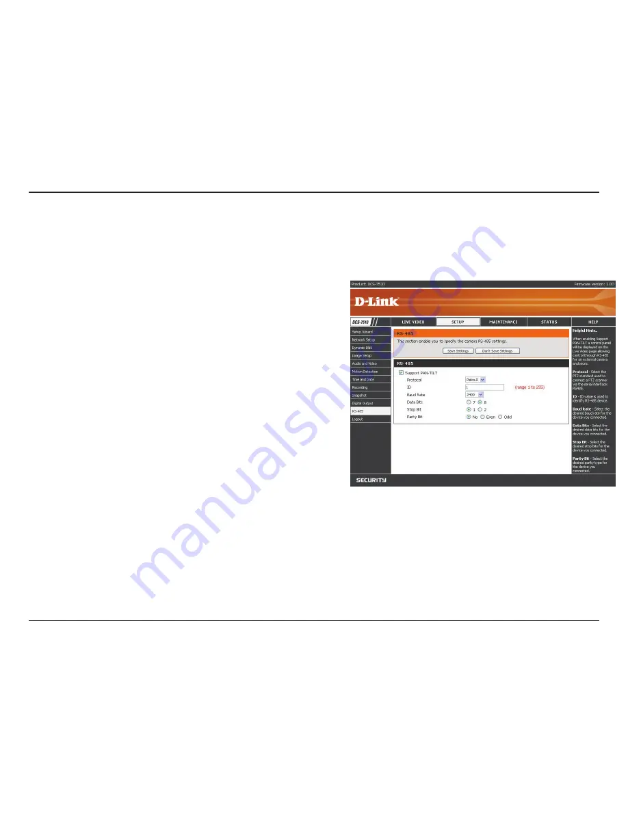
SETUP > RS-485
You may configure the
RS-485
settings or communication specifications (baud rate, data bit, stop bit, and parity bit)
for your camera. RS-485 is a serial communication method for computers and devices. For your camera, RS-485 is
used to control a PAN/TILT device, such as an external camera enclosure to perform PAN and TILT movement.
Once you enable this feature, a control panel will be displayed
on the
Live Video
window that provides control over an external
camera enclosure through the RS-485 signals.
Select the protocol type from the drop-down box.
This is the identifier for each RS-485 device. The ID range is from
1
to
255
.
Enter the
Baud Rate
settings required by your RS-485
equipment. If you are not sure what settings to use, check your
RS-485 equipment’s User Manual. The default value is
2400
.
The range is from
2400
to
38400
bps.
Enter the
Data Bit
settings required by your RS-485 equipment.
If you are not sure what settings to use, check your RS-485
equipment’s User Manual. The default value is
8
.
Enter the
Stop Bit
settings required by your RS-485 equipment.
If you are not sure what settings to use, check your RS-485
equipment’s User Manual. The default value is
1
.
Enter the
Parity Bit
settings required by your RS-485 equipment.
If you are not sure what settings to use, check your RS-485
equipment’s User Manual.
For example, if the data is 011, for even parity, the parity bit is
0 to keep the number of logic-high bits even. If the parity is odd,
the parity bit is 1, resulting in 3 logic-high bits.
Support PAN-
TILT:
Protocol:
ID:
Baud Rate:
Data Bit:
Stop Bit:
Parity Bit:
Click
Save Settings
to save your changes, or click
Don’t Save Settings
to discard your changes.
Содержание DCS-7410
Страница 1: ......
Страница 16: ...16 D Link DCS 7510 User Manual Section 2 Installation Click Finish to complete the installation Click Finish ...
Страница 19: ...19 D Link DCS 7510 User Manual Section 2 Installation Click Next Click Next ...
Страница 20: ...20 D Link DCS 7510 User Manual Section 2 Installation Click Next Click Next ...
Страница 21: ...21 D Link DCS 7510 User Manual Section 2 Installation Click Next Click Next ...
Страница 23: ...23 D Link DCS 7510 User Manual Section 2 Installation Installing Click Finish ...


