background image

10BASE-T Stackable Hubs 


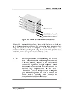
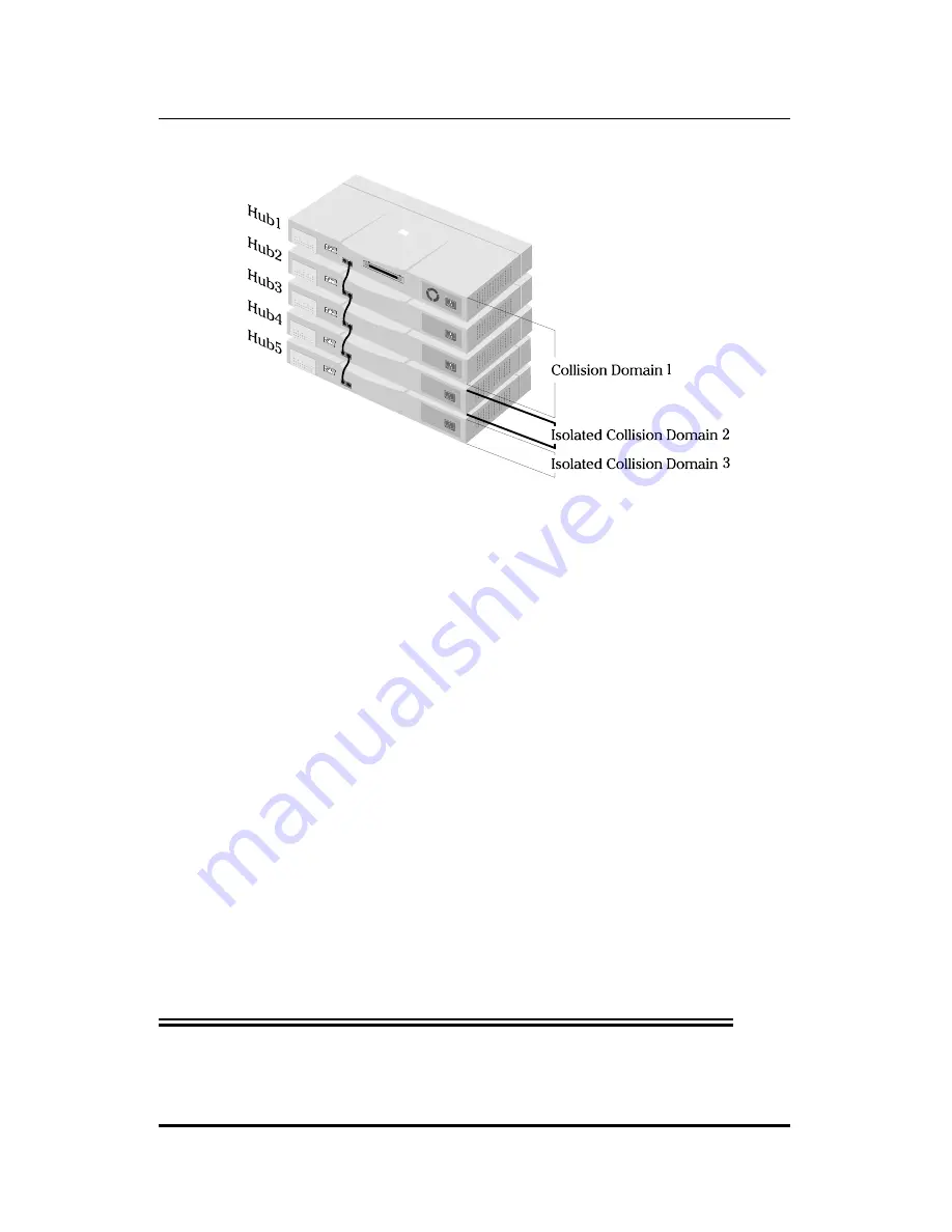
Figure 4 -4  Three Separate Collision Domains 

When a hub is segmented from the rest of the stack, the Segmented indicator 
on the front panel display will light.  For information about segmenting hubs 
using the console interface, see Chapter 6 in this 

User's Guide

.  For 

information about segmenting hubs using the network management module 
for the hub, see the management module's 

User's Guide


NOTE:  

Hub segmentation is controlled by the master 
hub.  While the hub is performing its Power-On 
Self-Test (POST), all hubs in the stack will be 
connected together in a single segment.  When 
the master hub completes its initialization, it will 
restore any segmentation of the hubs. 


Therefore, if you are using a switch or bridge to 
join different segments, be sure to enable the 
IEEE 803.1d Spanning Tree Protocol to 
prevent temporary network loops. 

Building Hub Stacks 

4-7 

Содержание 1824i - Hub - EN

Страница 1: ...10BASE T Stackable Hubs Intelligent Series User s Guide Rev 02w Oct 2004 6SNMPT 01 Printed In Taiwan RECYCLABLE ...

Страница 2: ...s uses and can radiate radio frequency energy and if not installed and used in accordance with this user s guide may cause harmful interference to radio communications Operation of this equipment in a residential area is likely to cause harmful interference in which case the user will be required to correct the interference at his own expense CE Mark Warning This is a Class A product In a domestic...

Страница 3: ... 2 Innovative Display 1 2 Security 1 2 Highlights 1 3 General Highlights of the Intelligent Series 1 3 2 EXTERNAL FEATURES AND INDICATORS 2 1 Front and Back Panel Layouts 2 1 Front Panel Indicators 2 3 3 SETTING UP THE HUB 3 1 Power and Environmental Requirements 3 1 Power Connection 3 2 Free standing Installation 3 3 Rack Mounting 3 3 Installing the Transceiver Tray 3 4 Table of Contents iii ...

Страница 4: ...Twisted pair Cabling 5 4 Using Thin Coaxial Cabling 5 5 Using Fiber or Thick Coaxial Cabling 5 6 Multilevel Cascading 5 6 6 USING THE CONSOLE INTERFACE 6 1 Connecting to the Hub 6 1 Console Usage Conventions 6 2 Logging in to the Hub Console 6 3 Logging In 6 3 Changing your Password 6 5 Setting up the Master Hub 6 6 TCP IP Settings 6 6 Out of band management and console settings 6 9 Software Updat...

Страница 5: ... Monitoring the Hub Stack 6 24 Displaying Segment Group and Port Statistics 6 21 Displaying Node Tracking Information 6 28 Resetting the Hub 6 29 System Reset 6 29 Factory Reset 6 30 A SPECIFICATIONS A 1 B POWER ON SELF TEST B 1 C BOOT CONFIGURATION FILE C 1 D CABLES AND CONNECTORS D 1 Crossover Cable D 2 Daisy chain Cable D 3 RS 232 DB9 Pin Specification D 3 0 Table of Contents v ...

Страница 6: ...text applies to both models Model numbers are normally used only to differentiate between models Overview of the User s Guide The User s Guide is divided into the following chapters and their related audiences Chapter 1 Introduction Describes the features of the Intelligent Stackable Managed Hubs Chapter 2 Indicators Introduces the layout of the hub s front panel rear panel and display indicators ...

Страница 7: ...nfigure the hub and a manageable stack using the console program Appendix A Product Specifications Provides information on the physical and electrical specifications of the hubs Appendix B Power On Self Test Provides information about the POST messages used for troubleshooting problems with the hub Appendix C Boot Configuration File Describes the hub boot configuration file Appendix D Cables and C...

Страница 8: ......

Страница 9: ...imizing network performance Overview Important features of the Intelligent Series include Media Connection Flexibility The Intelligent Series hubs support multiple Ethernet media types with twelve or twenty four ports for twisted pair cabling and one AUI port which provides connectivity for a variety of Ethernet wiring environments from basic workgroups to remote branch offices An appropriate exte...

Страница 10: ...play Intelligent Series hubs are equipped with a large clear display that shows an extensive array of information at a glance including link receive and partitioning status bandwidth utilization collision ratio runt occurrences and data transmission errors Security The Intelligent Series supports intrusion control Intrusion Control prevents unauthorized individuals from accessing the network Throu...

Страница 11: ...hain cabling Allows a total distance of 100 meters between the first hub and the last hub in the daisy chain Expandable network capacity up to 8 hubs in a single stack for a maximum of 192 ports and 8 AUI ports Recessed AUI connector in the rear of the unit Accommodates most standard Ethernet transceivers Allows the transceiver to be safely and conveniently tucked away A custom tray is provided fo...

Страница 12: ...sily removed and replaced with a new one should damage occur Automatic voltage selection 100V 240V AC 50 60Hz without fuse changes or manual voltage range settings Slim profile usable as a standalone desktop unit or as a rack mountable unit FCC Class A compliant CE Mark compliant VCCI Level 1 compliant Hub IDs are automatically assigned during initialization or when daisy chain links are changed O...

Страница 13: ...up Management To maximize management uptime two master hubs can be put in the same stack If the first one goes down the backup hub can automatically take over to provide uninterrupted traffic monitoring and network control Introduction 1 5 ...

Страница 14: ......

Страница 15: ...etail Figures 2 1 2 2 and 2 3 show the layouts of the front panel rear panel and display of the stackable hubs Note that there are variations in the appearances of the front and back panels between hubs in the series Only the 24 port models are depicted in this User s Guide Front and Back Panel Layouts Uplink Switch 10BASE T Ports LED Panel Figure 2 1 Front Panel Layout Setting Up the Hub 2 1 ...

Страница 16: ...which connect to workstations and servers using straight through cables and to other hubs using crossover cables Port 1 Uplink Switch Converts port 1 to an uplink port to allow you to connect the hub to an Ethernet switch or another hub with an ordinary straight through cable instead of a modified crossover cable RS 232 Console Port manageable models only Used to connect the master hub to a networ...

Страница 17: ...to be safely and conveniently tucked away Daisy chain Port The daisy chain port consists of one set of two RJ 45 connectors It allows you to connect Intelligent hubs together into a stack of up to 8 hubs with a maximum of 192 10BASE T ports Expansion Module Port manageable models only Used for adding optional expansion modules to the hub such as the 10 100Mbps switch module Front Panel Indicators ...

Страница 18: ... there is a problem with the link the indicator is off Receive The indicator of a port blinks green when the port is currently receiving packets on the connected segment Upon reception each data packet will be transmitted through all other connected ports on the hub or in the hub stack Auto partition The indicator of a port blinks amber when the port is automatically partitioned due to an abnormal...

Страница 19: ...ageable models only The Master indicator lights to indicate that the master hub is serving as an active master Console manageable models only The master hub s Console or Out Of Band indicator will light to indicate whether the hub s RS 232 console port is being used for the console interface or for out of band network management using the SLIP protocol The mode of the console port may be set using...

Страница 20: ...ays the percentage utilization of Ethernet bandwidth comparing the amount of data being transmitted over the network with the maximum amount possible All received Ethernet frames are counted whether they were valid or not The hub updates this display every 0 5 seconds HUB ID The HUB ID display indicates the Unit ID of the hub In a hub stack each hub unit should have a unique ID The hub is capable ...

Страница 21: ...her into a single Ethernet collision domain through the daisy chain connectors on the back Segmenting a hub places it in its own collision domain while allowing it to be managed with the rest of the stack External Features and Indicators 2 7 ...

Страница 22: ...ions per second Collisions occur whenever two or more devices on the network attempt to transmit at the same time whenever that happens all of the devices involved back off and retransmit after a small delay An excessive number of collisions can drastically reduce the bandwidth of the network and may indicate that the network is overloaded or that there is some sort of hardware or wiring problem T...

Страница 23: ... cord does not exceed the maximum length allowed in the country of operation The power cord normally included with the device is 1 83m 6ft long Also make sure it is terminated with the proper connector for use with your particular voltage and current requirements The cord voltage and current ratings should conform to the standards of the country where you are using the hub When using a 230V power ...

Страница 24: ...ure 32o to 122oF 0o to 50oC Humidity 5 to 95 non condensing Power Connection To connect power take the following steps 1 Plug the female IEC connector of the power cable into the power connector on the back of the hub 2 Insert the three pronged plug on the power module cable into a non switched grounded power outlet on a wall a power strip or a grounded extension cord 3 When you plug in the power ...

Страница 25: ...bber foot about 1 inch from each corner Rack Mounting The hubs can be used standalone on a tabletop or shelf or mounted in a rack When mounting the hub stack in a rack confirm that the rack is an EIA standard 19 inch rack For rack mounting convenience a pair of mounting brackets is included in the package Attach the mounting brackets with the enclosed machine screws and then mount the hub in the r...

Страница 26: ...g the transceiver easier a transceiver tray has been included with the hub To install a transceiver using the tray first place the transceiver in the tray with the slotted stubs on the transceiver s male AUI connector fitting into the slots on the front of the tray Open the door covering the AUI port and slide the tray and transceiver into the slot until the connection is secure Most transceivers ...

Страница 27: ...Phillips screwdriver remove the screws securing the power supply to release the unit 4 Remove the power supply by sliding it out the rear of the chassis Do not plug in the power supply when it is outside the chassis Doing so could cause personal injury or damage to the power supply 5 Slide the replacement power supply into the chassis engaging the connector carefully 6 Attach the power cord to the...

Страница 28: ......

Страница 29: ...entire hub stack counts as a single repeater hub when planning your network The Ethernet standard requires that there be at most four repeaters between any two stations on the network Using the hub s built in daisy chain ports allows you to link eight hubs together without violating the repeater count limitation This chapter tells about the various roles hubs in the stack can play how to connect t...

Страница 30: ... or indirectly through the IN port of a hub can be considered upstream of that hub and all hubs connected directly or indirectly through the OUT port of the hub can be considered downstream If a hub does not have any upstream hubs it is at the head of the stack Master Hub Roles You can include more than one master hub in a hub stack This allows you to continue to manage the hub stack even if the m...

Страница 31: ...u will not be able to control or monitor any slave hubs upstream of the master hub Each master hub has its own IP address All master hubs respond to SNMP management commands though only the Active Master is capable of controlling and monitoring other hubs If the Active Master hub fails then you will need to use the IP address of the new Active Master to manage the other hubs in the stack Slave Hub...

Страница 32: ...ack Hubs are daisy chained together using ordinary 4 pair Category 5 twisted pair cabling with RJ 45 connectors on each end A short 30cm daisy chain cable is included with the hub If you need to make a longer cable consult the pinout information in Appendix D The total length of all the cables measured from the first hub in the stack to the last must not exceed 100 meters Normally the master hubs ...

Страница 33: ...et stations on a single Ethernet network segment may give slow response at peak network loads Therefore the hub provides a way to segment hubs from the stack into their own collision domains Segmenting hubs requires only a simple management command and does not require any hardware or wiring changes Though the hubs continue to be daisy chained together and are managed as a single unit each hub can...

Страница 34: ...om Collision Domain 1 hubs 1 2 and 3 using the hub segmentation capability putting them into their own isolated Collision Domains 2 and 3 respectively A switch bridge or router can be used to connect the three collision domains so that traffic can pass between them yet keeping them isolated to reduce congestion on each segment Without an additional connection none of the three Collision Domains wi...

Страница 35: ...ork management module for the hub see the management module s User s Guide NOTE Hub segmentation is controlled by the master hub While the hub is performing its Power On Self Test POST all hubs in the stack will be connected together in a single segment When the master hub completes its initialization it will restore any segmentation of the hubs Therefore if you are using a switch or bridge to joi...

Страница 36: ......

Страница 37: ...hielded twisted pair cable STP or UTP The X label marked on each port means the ports are MDI X ports which connect to workstations and servers using straight through cables and to other hubs using crossover cables To connect to a network station use ordinary Ethernet twisted pair cable Category 3 or better either directly or through a central wiring patch block The cable can be a maximum of 100 m...

Страница 38: ...ion for the port should light If it does not then 1 Be sure that the connectors are seated correctly at both ends of the cable 2 Check the continuity of the wires in the cable as well as the pin assignments on the RJ 45 connectors 3 Be sure that the network station to which the port is connected is plugged in and powered on 4 Check that the right type of cable is connected to the port and that the...

Страница 39: ...e the network into separate collision domains Using Twisted pair Cabling One way you can connect hubs or 12hub stacks together is by using ordinary twisted pair cabling This is the simplest method though it has the disadvantages that the distance between hub stacks can be at most 100 meters and all but the first and last hubs require two RJ 45 ports each for the cascade connections Twisted pair ca...

Страница 40: ...one end of the straight through cable Port 1 of the hub and connect the other end of the cable to an ordinary non uplink port on the other repeater hub or Ethernet switch Don t try to cascade more than four repeater hub stacks in a line using twisted pair cabling Instead use a multilevel cascading scheme as discussed in the Multilevel Cascading section below Figure 5 3 Connection Through Port 1 5 ...

Страница 41: ... Coaxial Cabling Similarly transceivers connected to the AUI port can be used for connecting thick coax Ethernet 10BASE5 or fiber optic cabling FOIRL or 10BASE FL to the hub A thick Ethernet trunk can be up to 500 meters long preferably a single piece of cable and should have 50 ohm terminating resistors at each end The cable shield should be grounded at one end 10BASE5 transceivers usually tap di...

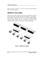
Страница 42: ... stations on the network goes through more than four repeaters For example a backbone level of hubs can be connected in a bus using 10BASE2 cabling and second level workgroup hubs can be connected to the backbone hubs using twisted pair cabling This type of network layout allows a greatly expanded number of network nodes without sacrificing manageability Figure 5 4 Multilevel Cascading 5 6 Network...

Страница 43: ...to set up the hub for management using SNMP View or another SNMP based network management system This chapter describes how to use the console interface to access the hub change its settings and monitor its operation Connecting to the Hub You can use the console interface by connecting the hub to a VT100 compatible terminal or a computer running an ordinary terminal emulator program e g the termin...

Страница 44: ...tems after a colon are read only values displayed for information purposes The cursor cannot be moved to these items 2 Items in angle brackets can be toggled on or off using the space bar 3 Items in square brackets can be changed by typing in a new value You can use the backspace and delete keys to erase characters behind and in front of the cursor 4 The up and down arrow keys the left and right a...

Страница 45: ...is means that before you can access the functions of the hub you will need to first log into the hub giving a password This section tells how to log onto the hub and how to change your password Logging In When you first connect to the hub it will display the login screen Figure 6 1 Login Screen To log in 1 Type in your user name and press Enter 2 Type in your password and press Enter Using the Con...

Страница 46: ... reset the hub settings using the Factory Reset NVRAM to Default Value menu selection Be sure to change this user name and password as described below to protect the security of your hub There are two levels of user privileges Super User and General User The default user SNMP T has Super User privileges Some menu selections available to users with Super User privileges may not be available to Gene...

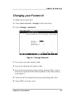
Страница 47: ...word 1 Type in your user name and press Enter 2 Type in your old password and press Enter 3 Type in the new password you have chosen and press Enter Type in the same new password in the following blank to verify that you have not mistyped it 4 Choose the SAVE command to let the password change take effect 5 Choose EXIT to exit this screen Using the Console Interface 6 5 ...

Страница 48: ... console port for out of band communication Each of the fields on this menu takes effect the next time the system is restarted Fields that can be set include IP Address determines the IP address used by the hub for receiving SNMP and Telnet communications Should be of the form xxx xxx xxx xxx where each xxx is a number represented in decimal between 0 and 255 This address should be a unique addres...

Страница 49: ...ssible outside your local network you can leave this field blank Send BOOTP Request Upon Power Up determines whether the hub should send out a BOOTP broadcast request when it is powered up The BOOTP protocol allows IP addresses network masks and default gateways to be assigned on a central BOOTP server if this option is set the hub will first look for a BOOTP server to provide it with this informa...

Страница 50: ...will be used the next time the hub is restarted Applies only when the serial port is being used for out of band SLIP management it does not apply when the port is used for the console port Available speeds are 1200 2400 9600 and 19200 bits per second Out of Band Dial Up Phone Number stored as a reference for the benefit of the system manager does not actually cause the hub to dial out System Resta...

Страница 51: ...rol this feature The fields you can set in this menu are Software Update Determines whether or not the hub will try to look for a configuration file over the network If set to Disable none of the fields below have any effect Software Update Mode Set to either Network or Out of band Determines whether the configuration file should be obtained through the Ethernet network or through the console port...

Страница 52: ... of the configuration file on your TFTP server If you are using SNMP View as your TFTP server this is the pathname of the CFG file on your hard disk This entry is used only if your boot protocol is TFTP ONLY if you are using BOOTP TFTP mode or if Use Bootp to get IP after start up is enabled the pathname will be obtained from the BOOTP server For more information about SNMP configuration files con...

Страница 53: ...esponds to the SNMP MIB II variable system sysName and is used to give a name to the hub for administrative purposes The hub s fully qualified domain name is often used provided a name has been assigned System Location corresponds to the SNMP MIB II variable system sysLocation and is used to indicate the physical location of the hub for administrative purposes System Contact corresponds to the SNM...

Страница 54: ...ptional events occur such as when the hub is powered on or when an SNMP request is made using an unknown community name The hub allows traps to be routed to up to four different network management hosts Figure 6 8 SNMP Trap Manager Menu The following trap parameters can be set IP Address gives the IP address of the network management station to receive the trap SNMP Community String determines the...

Страница 55: ...e hub If the hub receives a request with a community name it doesn t recognize it will trigger an authentication trap The SNMP allows up to four different community names to be defined and the access rights for each community can be separately set to either read only or read write The community names public and private are defined by default you can change these names in addition to adding others ...

Страница 56: ...n user however in order to prevent accidentally deleting all of the users with Super User privilege and making it impossible to change important hub settings Only users with the Super User privilege can add new and delete users To add a new user 1 Choose User Account Change from the main menu Figure 6 10 User Account Change Menu 1 Choose Create New User from the User Account Change menu 2 Enter th...

Страница 57: ...e user addition take effect 2 Choose EXIT to leave the Create New User menu To delete a user 1 Choose User Account Change from the main menu 2 Choose Delete Users from the User Account Change menu 3 Toggle the Delete field of the user you wish to remove to Yes Using the Console Interface 6 15 ...

Страница 58: ...hub can be viewed and controlled using the Group Configuration Primary Backup Master Menu and Port State menus Primary and Backup Master Hubs The Primary Backup Hub screen accessible from the Network Monitoring menu is used to display the status of each of the master hubs in the stack The primary master hub is labeled Primary Master backup master hubs are labeled Backup Master and non functioning ...

Страница 59: ...cator flash The items displayed on this screen are Group ID indicates which hub group is being displayed Group Serial Number gives the serial number of the displayed hub Group Description gives a description of the given hub showing how many ports it has and what options are available such as whether or not it is a master hub Group Role shows what role the hub is currently serving in the hub stack...

Страница 60: ...ows at what time the hub was last added to or removed from the stack The format is hh mm ss xx with hh representing hours since the master hub was powered on mm the minutes ss the seconds and xx representing 100ths of a second Group ID LED Flash Control a toggle allowing you to turn Group ID flashing on or off You can turn on Group ID flashing for a particular hub in order to help you find that hu...

Страница 61: ...nected to the port and Down otherwise Link Test State toggle control used for controlling whether or not the port requires link pulses If this field is set to Enable the port will check for link pulses and will only transmit if there is a good link to another station If the field is set to disabled Link Test will always display Up the link indicator will always be lit and the hub will always trans...

Страница 62: ...s to switch to another hub or the PREV PORT and NEXT PORT commands to switch to another port You can also enter the port s Group ID and Port ID numbers Segmenting Hubs Normally all hubs in the stack are connected together into a single Ethernet collision domain through the daisy chain connections However in some applications you may want to separate the hubs into separate collision domains while k...

Страница 63: ...er The Segmented indicator on the front panel should light indicating that the hub is now in a separate collision domain More information on segmenting hubs can be found in Chapter 4 Monitoring the Hub Stack The hub supports several monitoring functions allowing you to keep statistics on the operation of each port each hub and the entire network segment as well as to monitor the addresses of the p...

Страница 64: ...ware problem Very Long Event counts events where a signal is received longer than the jabber lockup protection timer 4 7 5 ms This may indicate noise on the line or a bad Ethernet interface Short Event counts events where less than 10 bytes are received and the frame start delimiter is invalid or where the start frame delimiter is valid but less than 2 bytes are received This may indicate noise on...

Страница 65: ...een frames Jabber counts frames longer than the maximum 1518 bytes octets with either bad framing or an invalid CRC Auto Partition counts events where the port was partitioned off from the rest of the network due to excessive errors Fragment counts packets less than 64 bytes with either bad framing or an invalid CRC These are normally the result of collisions DRM Data Rate Mismatch counts events w...

Страница 66: ...otal Errors sum of the FCS Error Alignment Error Too Long Frame Short Event Late Event Very Long Event and Data Rate Mismatch counters Figure 6 17 Port Statistics Display For the Segment Statistics display an additional item is displayed Interhub Collision counts the number of collisions that occur on the hub stack s internal management bus You can use the PREV GROUP NEXT GROUP PREV PORT and NEXT ...

Страница 67: ...tocol The Type Len field is used to display the length field from the Ethernet frame values in hex represent protocol numbers and values in decimal represent the packet length Different network protocols assign different meanings to this field Figure 6 18 Node Tracking Information A maximum of 12 entries can be displayed per port Entries older that the Mode Age Timer are removed the default value ...

Страница 68: ...ing the hub off and back on again or a Factory Reset which sets all of the hub s parameters to what they were when the hub was delivered from the factory System Reset To perform a System Reset 1 Choose System Reset from the main menu Figure 6 19 System Reset 1 Move the cursor to Yes to confirm the reset and press Enter The hub should restart 6 26 Using the Console Interface ...

Страница 69: ...ters SNMP parameters the enabled disabled settings of ports security settings etc will be erased and restored to their factory default settings 1 Choose Factory Reset NVRAM to Default Value from the main menu Figure 6 20 Factory Reset 1 Move the cursor to Yes to confirm the reset and press Enter The hub should restart and all of its parameters will be reset to their default values Using the Consol...

Страница 70: ......

Страница 71: ...ch TP Port Link Y Y Y Y For each TP AUI Port Data reception Y Y Y Y Auto Partition Y Y Y Y Manual Partition Y Y Y Y Daisy chain Link Y Y Y Y Collision Y Y Y Y Utilization Y Y Y Y Hub Unit ID Y Y Y Y Standby Master N Y N Y Console Out of band N Y N Y Feature SNMPT12 SNMPT12i SNMPT24 SNMPT24i RS 232C port configuration N A DB 9 DCE 9600 bps Async no parity 8 bits 1 stop bit N A DB 9 DCE 9600 bps Asy...

Страница 72: ...kManagement SNMPT12 SNMPT12i SNMPT24 SNMPT24i RFC 1157 SNMP RFC 1155 SMI RFC 1213 MIB II RFC 1368 Repeater MIB SNMP Proprietary MIB N A Yes N A Yes In band Management No Yes No Yes Out of band Management No Yes No Yes Management CPU N A Yes N A IDT 79C3041 Boot EPROM N A Yes N A 128K Flash Memory for Firmware N A Yes N A 256K 512 K Management RAM Memory N A Yes N A 1024K Master or Passive in Casca...

Страница 73: ...ecksum Test PASSED DRAM 01024 KByte PASSED LED Display Test PASSED E2PROM Integration Checksum PASSED 29F040 512 Kbytes Flash Memory Installed PASSED Network Monitor SRAM Test PASSED DL P2517B NIC Test PASSED Expansion Module Test PASSED INTELLIGENT SYSTEM CONFIG AND RUN TIME IMAGE DOWNLOAD DUPLICATE IP CHECKING Hit CTRL C to stop system boot load IP Address 202 39 74 51 Subnet Mask 255 255 255 0 ...

Страница 74: ...age memory Failure of this test is not considered a fatal error and failure will not cause the hub to halt Hub parameters may be lost however 5 Flash Memory Test Port 5 Frame Tests the hub s flash memory used for storing the hub s run time image 6 Network Monitor SRAM Port 6 Frame Tests the memory used in the hub for collecting network statistics 7 DL P2517B NIC Test Port 7 Frame Tests the hub s i...

Страница 75: ...eters as needed otherwise the hub will wait ten seconds and restart 1 Get BOOTP Information Port 1 Frame Port 7 Frame The hub sends a BOOTP request to obtain its IP address network mask default IP gateway and boot configuration file name This step will be skipped if the hub is not configured to use the BOOTP protocol Error codes in this step include 1 Can t get BOOTP information from BOOTP Server ...

Страница 76: ...t perform out of band download when console mode is specified 1 Erase Flash Memory Port 4 Frame Port 10 Frame If a new image file was downloaded the hub needs to erase the flash memory in preparation for storing the image Error codes in this step include 1 Can t Erase Flash Memory 1 Write Flash Memory Port 5 Frame Port 11 Frame If a new image file was downloaded the hub needs to write the new imag...

Страница 77: ...memory in preparation for use This is the last step in the boot process Error codes in this step include 1 Local Flash Download Error Flash Memory Checksum Error 2 Local Flash Download Error Run Time Image Error Power On Self Test B 5 ...

Страница 78: ......

Страница 79: ...d on the server with a CFG extension It can be up to 10 kilobytes long Lines beginning with are considered comments which are ignored by the hub All other lines are commands which are interpreted by the master hub The configuration file commands accepted by the hub are sysdescr string Takes string as the System Name corresponding to the SNMP MIB II variable system sysName This field is used to giv...

Страница 80: ...nmpt image string Takes string which may be up to 64 characters long as the filename on the TFTP server of the image file to be used When the hub boots it will load the given image file from the server and execute it This command may be used to update the hub s software when a new version is available from SNMP ip netmask mask Uses mask as the network mask for the local network The mask should be ...

Страница 81: ...ermissions can be read for read only community access or write for read write community access clear ip trap manager table Removes all entries from the hub s trap manager list ip trap manager address community Adds the host at address to the hub s SNMP trap manager list Traps sent to the host will use community name community which may be a string up to 32 characters long node age timer n Sets the...

Страница 82: ......

Страница 83: ...able a maximum of 100 meters long with RJ 45 connectors at both ends You can use shielded twisted pair cable or 0 4 0 6 mm 22 26 AWG 8 wire unshielded twisted pair cable for the connection The following diagram and table show a standard RJ 45 receptacle connector and its pin assignments Numbering of the pins and contacts shown in the diagram correspond to the entries in the subsequent table Only p...

Страница 84: ...modified crossover cable is necessary With a crossover cable two pairs of wires are switched at one connector end Carry out the following steps to create a customized crossover twisted pair cable 1 Leave one end of the cable as is with the RJ 45 connector intact The wiring at just one end of the cable needs to be modified 2 At the other end of the cable connect wires 1 and 2 to contacts 3 and 6 re...

Страница 85: ... Daisy Chain OUT 1 Link IN Link OUT 2 Link OUT Link IN 3 Data Data 4 Management Management 5 Management Management 6 Data Data 7 ID ID 8 ID ID NOTE Pins 1 2 3 6 4 5 and 7 8 must be pairs splitting the cable will most likely cause errors RS 232 DB9 Pin Specification The RS 232 serial port of the hub uses a 9 pin female connector The port can be connected to a VT 100 type terminal a PC or a workstat...

Страница 86: ...ion to 9 Pin Serial Port Terminal PC Serial Port DTE DB 25 Console Port DCE DB 9 9 RXD 2 TxD 3 DTR 4 SG 5 DSR 6 RTS 7 CTS 8 DCD 1 RXD 3 TxD 2 DTR 20 SG 7 DSR 6 RTS 4 CTS 5 DCD 8 Figure D 5 Local Connection to 25 Pin Serial Port Modem DCE DB 9 Console Port Connector DCE DB 9 9 RXD 2 TxD 3 DTR 4 SG 5 DSR 6 RTS 7 CTS 8 DCD 1 9 RXD 2 TxD 3 DTR 4 SG 5 DSR 6 RTS 7 CTS 8 DCD 1 Figure D 6 Remote Modem Con...

Страница 87: ...ubs Cables and Connectors D 5 Modem DCE DB 25 Console Port DCE DB 9 9 RXD 2 TxD 3 DTR 4 SG 5 DSR 6 RTS 7 CTS 8 DCD 1 RXD 3 TxD 2 DTR 20 SG 7 DSR 6 RTS 4 CTS 5 DCD 8 Figure D 7 Remote Modem Connection to 25 Pin Serial Port ...

Отзывы: