Product User’s Manual –
1
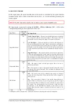
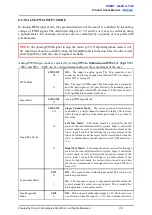
when the input is > 2.5V.
On
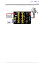
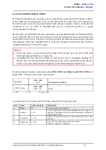
– Input 1 controls the speed of the motor. Motor stops when
the input is 0V and run at full speed when the input is 5V. Input
2 is digital input and it controls the direction of the motor. SW2
must be set to 0.
0 OFF
1 ON
X Don’t Care
* Left/Right is just for reference only. Actual side of the motor may depends on the Input signal.
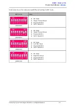
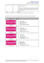
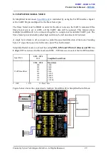
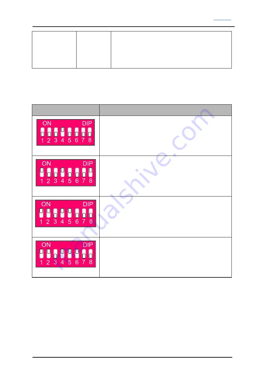
Table below shows the commonly used DIP switch settings for Analog/PWM mode.
DIP Switch
Mode
(00010000)
● Analog Mode
● Single Channel Mode
● Exponential Off
● SignMagnitude Mode Off
(10010001)
● PWM Mode
● Single Channel Mode
● Exponential Off
● SignMagnitude Mode On
(11011000)
● PWM Mode
● Left Mix Mode
● Exponential Off
● SignMagnitude Mode Off
(11011100)
● PWM Mode
● Right Mix Mode
● Exponential Off
● SignMagnitude Mode Off
Created by Cytron Technologies Sdn. Bhd. – All Rights Reserved
25


