background image

Page   of 

29

31

HHR-4X66 Single-lane Kits - Troubleshooting

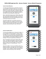
Reader to Base Communication Troubleshooting: 

The blue LED on the HHR-8066 reader shows the communication status between the reader and the HHR-8300/
HHR-8400 Base Unit. When the Blue LED is solid, the reader is not communicating with the Base Unit. When the Blue 
LED is flashing, the reader is communicating with the Base Unit.

Make sure the reader is powered on and in range of the Base Unit. Move closer to the Base Unit, until the reader is 
able to communicate with the Base Unit. 

Make sure the Base Unit is powered on and Board A and Board B are connected together. EXP(+) on Board A needs 
to be connected to EXP(+) on Board B, and EXP(-) on Board A needs to be connected to EXP(-) on Board B 
(HHR-8400 only). 

Present a valid credential to the IN Reader. Check the access controller log to verify that the credential was received 
on the correct port.

Present a valid credential to the OUT Reader. Check the access controller log to verify that the credential was 
received on the correct port.

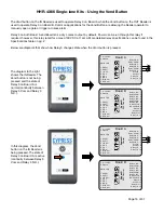
The reader to base communication can also be tested with the Vend feature.

Press the Vend button on the IN Reader, observe that Relay 3 on Board A has changed state. 
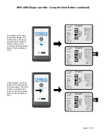
Press the Vend button on the OUT Reader, observe that Relay 3 on Board B has changed state (HHR-8400 only).

If the Vend button can activate Relay 3 on the appropriate board, it is is communicating with the Base Unit.

Wiegand Communication Troubleshooting:

Both Board A and Board B need to have proper Wiegand connections to the access controller. 

Make sure Board A and Board B have a common ground connection with the access controller. 

Make sure the D0 and D1 pins on Board A are connected to D0 and D1 on the access controller Wiegand 
port, and are not reversed. 

Make sure the D0 and D1 pins on Board B are connected to D0 and D1 on the access controller Wiegand 
port, and are not reversed (HHR-8400 only). 

If the access controller is not receiving the credential data, the next step is to check the Wiegand data voltage. 
The voltage on the D0 and D1 lines should idle at 5V, relative to ground, on both Board A and Board B. 

Use a volt meter to measure the DC voltage between D0 and ground, and D1 and ground on Board A.

Use a volt meter to measure the DC voltage between D0 and ground, and D1 and ground on Board B

If one or more of the data lines is below 4.5V, this could be the cause of the communication failure. 

Disconnect the low data line from the Base Unit and the access controller. 

Measure DC voltage between the low data line and ground on the Base Unit.

Measure DC voltage between the low data line and ground on the access controller.

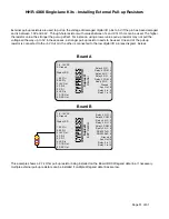
Typically, either the data line on the access controller or the Base Unit is damaged and will be low, while the 
other is normal at 5V. If the voltage on the low data line is between 1V and 4.4V, it can usually be recovered by 
installing an external pull-up resistor. If the voltage on the low data line is below 1V, it is likely grounded, and 
cannot be recovered with external pull-up resistors. 

Содержание HHR-4000

Страница 1: ...ars of Access Control Ingenuity CypressIntegration com 2021 Cypress Computer Systems 1778 Imlay City Road Lapeer MI 48446 800 807 2977 HHR 4000_Single_210920 Kit Part Numbers 1 Reader Single lane kit...

Страница 2: ...ing Dock Input 100 240 Vac 1A 50 60Hz Max Relays Max Switching 220Vdc 30W resistive 1A 250Vac 37 5VA 1A Running Spec with load 30Vdc 1A resistive 125 Vac 0 3A resistive 1x10⁵ operations 20 C Credentia...

Страница 3: ...oard A and Board B Pin Layout 9 HHR 8300 Wiring Diagram 10 HHR 8400 Wiring Diagram 11 LED Functions 12 Button Functions 13 Reading Credentials 14 Access Granted Access Denied Responses 15 Using the Ve...

Страница 4: ...network and no two identically received messages are accepted Handheld Reader Authentication State Linked to Authentication Attempt No message from the base station or from an attacker can cause the...

Страница 5: ...ion key HHR 8300 HHR 8400 Base Wireless Communication The wireless radios in the HHR 4000 readers and base units use the IEEE 802 15 4 standard for mesh networking The HHR readers and base units form...

Страница 6: ...r rate It is your responsibility to ensure the charger you purchased works properly If at any time a battery begins to heat smoke swell or balloon immediately stop charging the battery and disconnect...

Страница 7: ...Dock x1 HHR RCHL Wall Plug Charger x1 This kit has one HHR 8066 reader and the HHR 8300 single lane base HHR 4266 HHR 8066 Single lane Reader x2 HHR 8400 Dual lane Base x1 HHR DOCK Charging Dock x2 H...

Страница 8: ...tches J1 Header J2 Header J3 Header Status Diagnostic LED 1 8 16VDC 2 Ground Status LED 1 EXP 2 EXP 3 5V Out 4 P R 2 5 P R 1 6 LED In 7 D1 D Out 8 D0 C Out Relay 4 N O 1 Relay 4 COM 2 Relay 4 N C 3 Re...

Страница 9: ...Relay 1 In 10 Suprex Central 1 8 16VDC 2 Ground Status LED 1 EXP 2 EXP 3 5V Out 4 P R 2 5 P R 1 6 LED In 7 D1 D Out 8 D0 C Out Relay 4 N O 1 Relay 4 COM 2 Relay 4 N C 3 Relay 3 N O 4 Relay 3 COM 5 Rea...

Страница 10: ...Panel N O COM Ground LED 2 Out LED 1 Out Data 1 Data 0 1 8 16VDC 2 Ground Status LED 1 EXP 2 EXP 3 5V Out 4 P R 2 5 P R 1 6 LED In 7 D1 D Out 8 D0 C Out Relay 4 N O 1 Relay 4 COM 2 Relay 4 N C 3 Rela...

Страница 11: ...P R 2 5 P R 1 6 LED In 7 D1 D Out 8 D0 C Out Relay 4 N O 1 Relay 4 COM 2 Relay 4 N C 3 Relay 3 N O 4 Relay 3 COM 5 Realy 3 N C 6 RS 232 TxD 7 RS 232 RxD 8 Ground 9 Aux Out 10 Relay 2 In 11 Relay 1 In...

Страница 12: ...knowledge Red LED and Green LED credential read indicator Red and Green LEDs fl ashing once indicates that a credential has been read by the HHR reader Base Unit Diagnostic LED Functions Board A and B...

Страница 13: ...d when the Handheld Reader is powered on Vend Button Allows the user to operate a door or a gate or other equipment in the area This needs to be con fi gured by the installer When pressed Relay 3 on t...

Страница 14: ...e red and green LEDs will fl ash once and the reader will emit a medium pitch beep When the HHR 8066 reader is communicating with the Base Unit indicated by the fl ashing blue LED the credential data...

Страница 15: ...ted Response while the HHR reader is set to OUT Mode Access Denied Response The Access Denied Response is controlled by the Relay 1 In pin on the Base Unit When the Relay 1 In pin is an active low dig...

Страница 16: ...y 3 on Board A is active continuity between Relay 3 Com and Relay 3 N O 1 8 16VDC 2 Ground Status LED 1 EXP 2 EXP 3 5V Out 4 P R 2 5 P R 1 6 LED In 7 D1 D Out 8 D0 C Out Relay 4 N O 1 Relay 4 COM 2 Re...

Страница 17: ...Central 1 8 16VDC 2 Ground Status LED 1 EXP 2 EXP 3 5V Out 4 P R 2 5 P R 1 6 LED In 7 D1 D Out 8 D0 C Out Relay 4 N O 1 Relay 4 COM 2 Relay 4 N C 3 Relay 3 N O 4 Relay 3 COM 5 Realy 3 N C 6 RS 232 Tx...

Страница 18: ...can supply 8 16Vdc 300mA Connect the power supply to the Board A in the HHR 8300 Bench Testing Steps 1 Power on the reader The blue LED will be on and solid when the reader is powered on The blue LED...

Страница 19: ...one second when an invalid credential is received on this Wiegand port D Vend Feature Connect Relay 3 COM and Relay 3 N O normally open to the access controller This relay output can be used to contr...

Страница 20: ...arm activates the door gate opens etc A volt meter in continuity mode can also be used determine the state of the relay When the Vend Button is pressed there will be continuity between Relay 3 COM and...

Страница 21: ...nit Use a battery to power the Base Unit and test the wireless connection between Base Unit and the Handheld Reader in the desired operating area 2 The Base Unit should be mounted at least 10 feet 3 m...

Страница 22: ...l bit to drill holes into the surface with a depth of at least 1 25 inches Place the wall anchors into the newly drilled holes b If not using wall anchors following the hole pattern in the diagram abo...

Страница 23: ...t connected to the LED In pin is con fi gured to activate for at least one second when a valid credential is received on this Wiegand port c Access Denied Response Connect an active low digital output...

Страница 24: ...ne Wiegand port on the access controller B Access Granted Response Connect an active low digital output to the LED In pin Alternatively a dry contact can be connected to the LED In pin and Ground Make...

Страница 25: ...on Board A is activated 4 Press and release the Vend button Verify that Relay 3 on Board A has changed state Observe that the duress alarm activates the door gate opens etc A volt meter in continuity...

Страница 26: ...HR 8066 reader uses a Lithium Polymer battery it is important that the HHR 8066 is charged only with the HHR RCHL see warning on page 6 The HHR RCHL has an LED indicator This LED will either display r...

Страница 27: ...cont The two pictures below show the charging contacts on the HHR DOCK and HHR 8066 The HHR 8066 sits in the HHR DOCK and the charging contacts connect The pictures below show the charging port on the...

Страница 28: ...66 Single lane Kits Battery Life and Charging cont The picture below shows the complete charging set up The HHR RCHL charger is plugged into an outlet and connected to the HHR DOCK and the HHR 8066 se...

Страница 29: ...iegand Communication Troubleshooting Both Board A and Board B need to have proper Wiegand connections to the access controller Make sure Board A and Board B have a common ground connection with the ac...

Страница 30: ...B when a valid credential is received If the connection to the access controllers is in place and working correctly the next step is to check is the idle voltage of the LED In pin The LED In pin idle...

Страница 31: ...s External pull up resistors are used to pull up the voltage of damaged digital I O pins to 5V if the pin has been damaged and is between 1 0V and 4 4V Through hole resistors with values between 1k an...

Отзывы: