

Page of
15
31
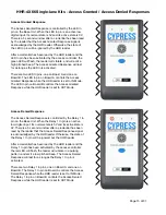
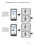
Access Granted Response
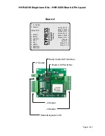
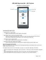
The Access Granted Response is controlled by the LED In
pin on the Base Unit. When the LED In pin is an active low
digital input. Its normal state is 5V and its active state is 0V.
There is a 5 second window after a credential has been read
by the reader that the Access Granted Response signal is
acknowledged by the HHR reader. Otherwise, the state of
the LED In pin will be ignored by the HHR reader.
After a credential has been read by the HHR reader and the
LED In pin has been activated by the access controller; the
green LED will flash, the reader will vibrate, and will emit a
high pitched beep. The Access Granted Response will last
for as long as the LED In is activated.
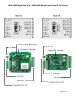
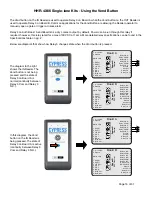
There are two LED In pins, one on Board A and one on
Board B. The LED In pin on Board A controls the Access
Granted Response while the HHR reader is set to IN Mode.
The LED In pin on Board B controls the Access Granted
Response while the HHR reader is set to OUT Mode.
Access Denied Response
The Access Denied Response is controlled by the Relay 1 In
pin on the Base Unit. When the Relay 1 In pin is an active
low digital input. Its normal state is 5V and its active state is
0V. There is a 5 second window after a credential has been
read by the reader that the Access Denied Response signal
is acknowledged by the HHR reader. Otherwise, the state of
the Relay 1 In pin will be ignored but the HHR reader.
After a credential has been read by the HHR reader and the
Relay 1 In pin has been activated by the access controller;
the red LED will flash, the reader will vibrate in a pulsing
pattern, and emit a low pitched beep. The Access Denied
Response will last for as long as the Relay 1 In pin is
activated.
There are two Relay 1 In pins, one on Board A and one on
Board B. The Relay 1 In pin on Board A controls the Access
Denied Response while the HHR reader is set to IN Mode.
The Relay 1 In pin on Board B controls the Access Denied
Response while the HHR reader is set to OUT Mode.
HHR-4X66 Single-lane Kits - Access Granted / Access Denied Responses


