

Page of
21
31
Tools Needed
Drill
Phillips Screwdriver
3/16” Drill Bit (if using wall anchors)
7/64” Drill Bit (if not using wall anchors)
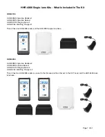
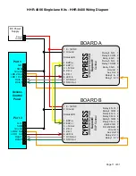
HHR-4X66 Single-lane Kits - Field Installation
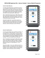
A. Determine Base Unit Location
1. The Base Unit should be mounted in a location which allows for the maximum range between the Base Unit and
the Handheld Reader.
Typical maximum range for the wireless connection between the Handheld Reader and the
Base Unit is 150 ft. (45 m) line-of-sight indoors, or 500 ft. (152 m) line-of-sight outdoors.
2. It is not recommended to locate the Base Unit directly above the area where the Handheld Readers will be used, as
this may cause communication problems.
3. The Base Unit location must accommodate a wired connection to the access controller (see Section C).
B. Mounting the Base Unit
1. It is recommended to temporarily set up the Base Unit at its desired mounting location to test communication with
the Handheld Reader before permanently mounting the Base Unit. Use a battery to power the Base Unit and test
the wireless connection between Base Unit and the Handheld Reader in the desired operating area.
2. The Base Unit should be mounted at least 10 feet (3 m) above the ground outdoors, or 6-8 feet (1.8 - 2.4 m) above
the floor indoors. If obstacles are present (such as vehicles, trains, building, trees, etc.) choose a location high
enough, or with good line-of-sight to avoid interference from these obstacles.
3. A non-metal mounting surface is recommended for the Base Unit, as metal surfaces reduce the e
ff
ective range
between the Base Unit and the Handheld Reader. If mounting the Base Unit on a metal surface is unavoidable, use
a non-metal spacer to space the Base Unit at least 2 inches (5 cm) from the metal surface.
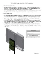
4. The Base Unit must be mounted in the upright position. When correctly oriented, the “Cypress” sticker can be
clearly read and the enclosure door will open to the left.
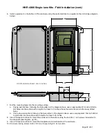
5. Remove the plastic backplate and circuit boards from the enclosure before drilling any holes in the enclosure to
avoid damaging the backplate or circuit boards. The backplate is held in place by 4 Phillips screws at each corner
of the enclosure.


