Getting Started With EZ-
BLE™ PRoC™ Module
www.cypress.com
Document No.: 001-96841 Rev. **
34
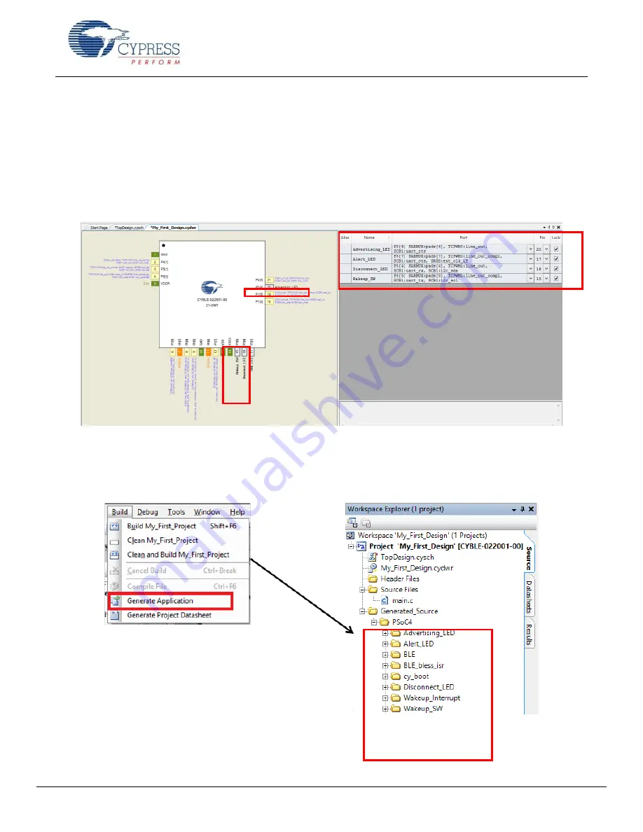
15. To assign pins to the LEDs and button, open the file
My_First_Project.cydwr
(Design-Wide Resource file) from
―Workspace Explorer‖ and click the
Pins
tab. You can use this tab to select the device pins for the outputs
(Advertising_LED, Disconnect_LED, and Alert_LED) and Wakeup_SW for input as
Figure 44
shows. The following pin
assignment is made with respect to the CY8CKIT-042 BLE pioneer kit and the CYBLE-022001-EVAL board connections.
The LEDs on the CY8CKIT-042 BLE baseboard are mapped to P3[6] (green), P3[7] (blue), and P2[6] (red) on the Pioneer
kit baseboard. These baseboard connections correspond to connections P3[6] (green), P3[7] (blue), and P3[4] (red) of the
CYBLE-022001-EVAL module. The LEDs are Active low. Wakeup_SW is mapped to P2[7] of the Pioneer Kit baseboard,
which is P3[5] of the CYBLE-022001-EVAL module. Refer to
CYBLE-022001-EVAL Connections to CY8CKIT-042-BLE
for
details on the EZ-BLE PRoC Module Evaluation board connections.
Figure 44.Pin Selection
16. Select
Generate Application
from the Build menu.
Notice in the
Workspace Explorer
window that PSoC Creator
automatically generates source code files for the Bluetooth Low Energy, Clock, and Digital Output/Input Pin Components,
as
Figure 45
shows.
Figure 45. Generated Source Files


