26
CY3280-SmartSense CapSense Auto-Tuning Kit Guide, Doc. # 001-64672 Rev. *B
A.1.2
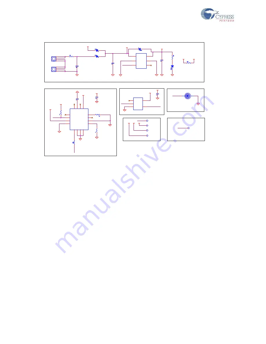
Power Supply
In the schematic:
■
CapSense controller CY8C20246A is used to detect finger touch on sensors BTN0-BTN3. It
drives active low LEDs (LED0-LED3) based on detected touch on sensors.
■
CY8C20246A controller can be powered either from on-board AAA batteries or from external
sources (VDD_EXT / VDD_DEV).
■
Supply from battery and VDD_EXT are gated by the Power button, but VDD_DEV is not.
■
CapSense controller CY8CMBR2044 is used to detect finger touch on the Power button. It turns
on/off series pass switch based on detected status. CY8CMBR2044 is configured to operate for a
period of 1 year on battery power.
■
Power LED turns on when any of the three power sources are activated.
■
Connectors J1 and J2 are expansion connectors. Unused I/Os of controller CY8C20246A are
routed to these connectors.
■
Connector J5 is used for ISSP programming of CY8C20246A. ISSP pins P1[0] and P1[1] are
routed to this connector.
■
If required, connector J5 can be reused as an I
2
C header. For this, configure P1[0] and P1[1] as
I
2
C pins in the PSoC Designer project. However, CapSense buttons, BTN1 and BTN2, cannot be
used. An alternative option is to configure P1[5] and P1[7] as I2C pins; both are mapped to J5.
■
It is not recommended to configure ISSP pins P1[0] and P1[1] as CapSense sensors. However
these pins are used as sensors in this kit only to demonstrate SmartSense self tuning capability.
■
SmartSense requires an external modulation capacitor Cmod, connected from VSS to one of two
dedicated PSoC pins P0[1] or P0[3]. The CY3280-SmartSense kit uses P0[3] as the Cmod (C4)
pin. The recommended value for the external modulation capacitor is 2.2 nF. A ceramic capacitor
must be used. The temperature capacitance coefficient is not important.
■
Cypress strongly recommends using a 560-
Ω
series resistor on all CapSense sensor traces to
suppress RF interference. This resistor must be placed as close to the CapSense controller as
possible.
1206R
D1
LED Red
2
1
Power Section
VDD_Dev
VDD_Dev
VDD_SW
TWO AAA 1.5V 1125mAh Battery
VIN
VIN
PWR_BTN
C2
0.1 uFd
Series Pass Switch
Power Button
VOUT
GN D
N C
EN
GND1
VIN
U4
MIC94090 SC-70-6
5
1
2
6
3
4
R6
ZERO
1
2
D8
DIODE SCHOTTKY
2
1
Shield
Sensor
B4
CapSense Button 13mm Round
1
VIN
VIN
R3
5.1K
1
2
U1
CY8CMBR2044
SCANRATE/SLEEP
12
VS
S
7
ARST
9
XRES
11
GPO0
2
TOGGLE/FSS
3
GP
O
3
14
GPO1
1
CS
0
5
CS3
10
CS
1
6
CS
2
8
VD
D
13
GP
O
2
16
CM
O
D
15
DELAY
4
Capsense Based Power Button (CY8CMBR2044)
PW
R
_
B
T
N
CM
O
D
1
C1
2200 pFd
R4
56
0E
PWR_ON_INV
VDD_Bat
Test Points
C6
10 uFd 16v
CMOD2
Place CMOD p ad nea r U1.
CMOD1
CMOD
U2
SN74LVC1GU04
NC
1
A
2
GND
3
VCC
5
Y
4
PWR_ON
VIN
C9
0.1 uFd
VIN
R7
ZERO
1
2
DN P
PWR_ON_INV
R1
5.1K
1
2
VIN
D3
DIODE SCHOTTKY
2
1
VDD_Bat
VDD_SW
R5
330 ohm
1
2
D2
DIODE SCHOTTKY
2
1
PWR_ON
R2
5.1K
1
2
VIN
VIN
J4
Battery Clip AAA
1
2
3
4
VDD_Ext
J3
Battery Clip AAA
1
2
3
4
VDD_Dev
VDD_SW
-
+
-
+
C7
10 uFd 16v
VDD_SW
COMN
C8
0.1 uFd
VDD_BAT
Содержание CapSense CY3280-SmartSense
Страница 8: ...8 CY3280 SmartSense CapSense Auto Tuning Kit Guide Doc 001 64672 Rev B Introduction ...
Страница 27: ...CY3280 SmartSense CapSense Auto Tuning Kit Guide Doc 001 64672 Rev B 27 A 2 Board Layouts A 2 1 PDC 09587 Top ...
Страница 28: ...28 CY3280 SmartSense CapSense Auto Tuning Kit Guide Doc 001 64672 Rev B A 2 2 PDC 09587 Bottom ...


