background image

8

Test Mode Select

Turn DIP switch 2 

on

 for Remote &/or Central

Default:

 Standard Wiegand

Turn on DIP switch 8 on both units

Keypad (Wiegand/No Filter)

Turn on DIP switch 7 on both units

F/2F (Unsupervised)

Turn on DIP switches 6, 7, 8 on both units

Strobed Rising Edge (MR-5)

Turn on DIP switches 7 and 8 on both units

Strobed Rising Edge (Dorado 644)

Turn on DIP switch 6 on both units

Strobed Rising (MagTek)

Turn on DIP switches 6 and 8 on both units

Strobed Falling Edge

Turn on DIP switches 6 and 7 on both units

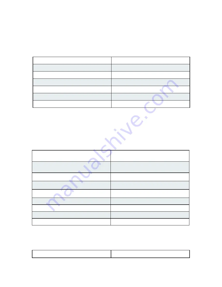
Configuration Mode settings

Standard Wiegand interface is the default setting. To use with non-Wiegand interface:

a) Power off both Suprex units.

b) Turn on DIP switch 1 on both units.
c) Set DIP switches as described below for appropriate interface:

d) Power on both Suprex units. Status LED should be solid green. 
e) Power off both Suprex units; return DIP switch 1 to 

off

 position on both units to select Run 

Mode settings. 

When switching to Run Mode, always reselect Run Mode settings. 

Central / Remote Select

Turn DIP switch 3 

on

 for Central Mode / 

turn 

off 

for Remote Mode

Remote Digital/Analog Relay Select  

Turn Remote Unit's DIP switch 2 

on

 for digital 

input / 

off 

for analog input

Supervision Relay (Relay 3, Central Unit)

Turn Central Unit's DIP switch 4 on for supervision 
relay / off for normal relay

Supervision Relay  (Relay 1, Remote Unit)

Turn Remote Unit's DIP switch 4 

on

 for supervision 

relay /

 off

 for normal relay

Pullup Resistor Select

Turn 

on

 DIP switch 5 to enable pullup resistors / 

off


to disable [applicable units)

EXP Select (for 

no

 EXP)

Turn 

off

 DIP switches, 6, 7, and 8 on both units

EXP Select (for 

1

 EXP)

Turn 

on

 DIP switch 8 on both units

EXP Select (for 

2

 EXPs)

Turn 

on

 DIP switch 7 on both units

EXP Select (for 

3-7

 EXPs)

See pg. 9

Run Mode settings 

Select Run Mode settings as described below, then power on both Suprex units to begin operating 
in Run Mode.

Cypress Suprex® RS-485 Series - Common Configuration and Run Mode Settings

Test Mode setting

See page 13 to troubleshoot using Test Mode.

Содержание 816684001659

Страница 1: ...x RS 485 SPX 7500 Wired Reader Extender Product Manual Cypress Integration Solutions 35 Years of Access Control Ingenuity CypressIntegration com 2019 Cypress Computer Systems 1778 Imlay City Road Lape...

Страница 2: ...O Interface Wiegand maximum 248 bits pass through Strobed Clock Data F 2F Unsupervised LED 0 30V Range and Cable Requirements Typical range of 4000 ft 22 AWG Shielded Twisted Pair Additional Features...

Страница 3: ...n Mode Settings 8 DIP Switch Map 9 Quick Reference for Typical Connections 10 Troubleshooting 11 Accessory I O I O Overview 12 Central Relay Inputs 13 Relay 1 2 I O 14 Remote Relay Inputs 15 Relay 3 4...

Страница 4: ...Series Physical Dimensions and Mounting Hole Locations All dimensions are listed in inches EXP Enclosure 0 120 X 4 4 125 2 890 3 155 2 121 2 364 EXP 2000 SPX 7500 Enclosure 0 120 X 4 3 065 2 770 4 06...

Страница 5: ...y 4 N O Relay 4 COM Relay 4 N C Relay 3 N O Relay 3 COM Relay 3 N C Ground Aux Output Relay 2 Input Relay 1 Input 8 16VDC Input Ground EXP EXP 5VDC Output Relay 4 Input Relay 3 Input LED Output D1 Dat...

Страница 6: ...e powered by a suitable power supply For testing purposes the units can share the same power supply Basic Bench Test During initial setup refer to the Run Configuration mode settings pgs 7 9 1 Connect...

Страница 7: ...ng properly Check that all connected EXPs are powered and properly connected For details on setting Configuration Mode see pgs 7 9 OPERATING MODES Wired Suprex products have 3 operating modes Run Mode...

Страница 8: ...select Run Mode settings When switching to Run Mode always reselect Run Mode settings Central Remote Select Turn DIP switch 3 on for Central Mode turn off for Remote Mode Remote Digital Analog Relay...

Страница 9: ...tion Mode setting the unit will need to be powered off turn DIP 1 on and other Configuration DIP Switches as needed power the unit on and the Status LED will be solid green The solid green LED means t...

Страница 10: ...Ground exp exp 5V Out P R 4 P R 3 LED In D1 Data Out D0 Clock Out Relay 4 N O Relay 4 Com Relay 4 N C Relay 3 N O Relay 3 Com Relay 3 N C Ground Aux Output Relay 2 Input Relay 1 Input Door Strike Out...

Страница 11: ...he access control panel data port are functional by directly connecting the reader to the data port and passing card data Check Suprex circuit boards for any signs of visual damage such as burnt trace...

Страница 12: ...vated and will hold this state for as long as the Relay Input is set to 0Volts The Relay Inputs can be tested by making a jumper connection to ground and monitoring the change in continuity of the Rel...

Страница 13: ...emote unit will be activated When the relay is activated the Relay Output pins will change continuity from N C and COM to N O and COM not shown in diagram Cypress Suprex RS 485 Series Accessory I O Ce...

Страница 14: ...xp 5V Out Relay 4 Input Relay 3 Input LED Out D1 Data In D0 Clock In Relay 2 N O Relay 2 Com Relay 2 N C Relay 1 N O Relay 1 Com Relay 1 N C Ground Aux Input Not Used Not Used Remote 8 to 16 VDC Groun...

Страница 15: ...ay output pins will change continuity from N C and COM to N O and COM not shown in diagram Relay 3 can used to send signals to the access panel while Supervision mode is active but it is important to...

Страница 16: ...Ground exp exp 5V Out P R 4 P R 3 LED In D1 Data Out D0 Clock Out Relay 4 N O Relay 4 Com Relay 4 N C Relay 3 N O Relay 3 Com Relay 3 N C Ground Aux Output Relay 2 Input Relay 1 Input Central 8 to 16...

Страница 17: ...ot Used pin is the new Relay 4 input pin Use the diagram below as a reference For most applications the analog relay inputs are sufficient But for instances where a significant delay is noticed in the...

Страница 18: ...O Signal Diagram below shows how this signal is passed through he SPX 7500 Ground LED Out Data1 Data 0 N O COM Access Control Panel Card Reader Power Ground LED IN Data 1 Data 0 LED I O Signal Diagram...

Страница 19: ...In pin The AUX I O Signal Diagram below shows how this signal is passed through the SPX 7500 AUX I O Signal Diagram Ground Input Data1 Data 0 N O COM Access Control Panel Card Reader Power Ground Out...

Страница 20: ...ormally closed contact at the Remote unit and the other example is monitoring a normally open contact at the Remote unit In the examples given a normally closed contact will require a programming resi...

Страница 21: ...x Central and Remote units must be configured with the total number of EXP pairs being used This is configured in the Run Mode settings and is controlled by DIP switches 6 7 and 8 Change settings on b...

Страница 22: ...N C Ground Aux Output Relay 2 Input Relay 1 Input 8 to 16 VDC Ground exp exp 5V Out P R 2 P R 1 LED In D1 Data Out D0 Clock Out Relay 4 N O Relay 4 Com Relay 4 N C Relay 3 N O Relay 3 Com Relay 3 N C...

Страница 23: ...k In Relay 2 N O Relay 2 Com Relay 2 N C Relay 1 N O Relay 1 Com Relay 1 N C Ground Aux Input Not Used Not Used 8 to 16 VDC Ground exp exp 5V Out Relay 4 Input Relay 3 Input LED Out D1 Data In D0 Cloc...

Отзывы: