background image


WPT-DB Installation Manual 

Document No. 910-00014-01, Rev. 04 


Page 4 of 20 


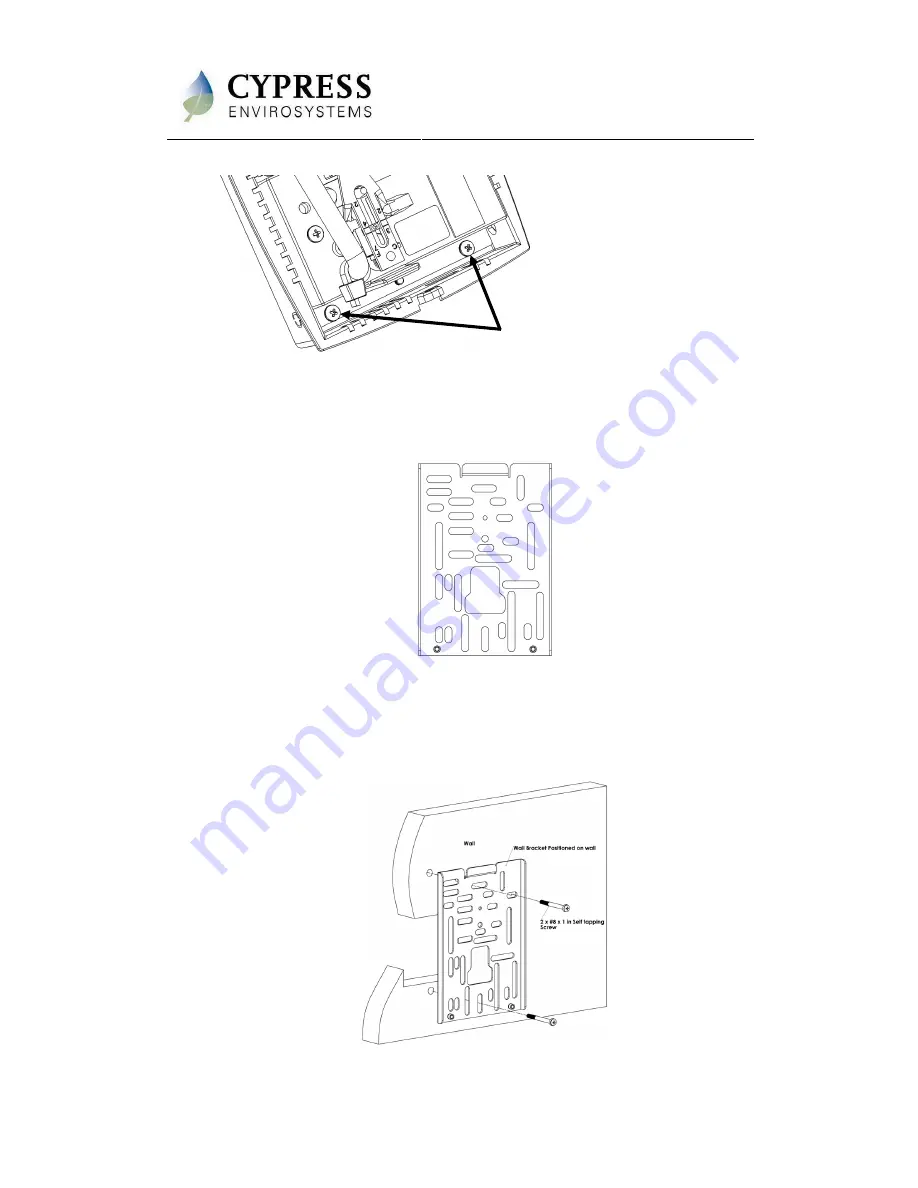
Figure 3. Removing the Universal Wall Bracket 

3.  Adjust  the  Universal  Wall  Bracket  against  the  old  thermostat  position,  such  that 

any two slots on the wall bracket match the existing two screw holes on the wall, 
and the  large center opening is  aligned  with the air tube(s).  The Universal Wall 
Bracket is shown in Figure 4. 


Figure 4. Universal Wall Bracket 

4.  Pull the air tubes through the central opening of the Universal Wall Bracket. 

5.  Affix the Universal Wall Bracket to the wall with two screws, as shown in Figure 5. 

Note:  The provided Wall Anchors can be used if existing receptacles are not in the 
correct location, or if they are damaged. 


Figure 5. Mounting the Universal Wall Bracket 

Unscrew these two screws to 
Dismount wall bracket from rear side
 

Содержание WPT-800-DB Series

Страница 1: ...of the legacy pneumatic HVAC systems 1 1 Components The WPT DB 800 Series kit includes the following components WPT DB Universal Wall Bracket Mounting screws 6 x 1 self tapping x2 Wall Anchors CR123 b...

Страница 2: ...may not have a lot of slack be careful that the tubes do not retract into the wall In a 2 pipe system note the positions of branch and main tubes ESD Handling Precautions Warning The WPT DB contains E...

Страница 3: ...ult if the end of the lever is allowed to move left or right by more than 1 16 Figure 2 WPT DB Lever 2 1 2 Installing the WPT DB The WPT DB is installed in the existing thermostat location using the U...

Страница 4: ...g is aligned with the air tube s The Universal Wall Bracket is shown in Figure 4 Figure 4 Universal Wall Bracket 4 Pull the air tubes through the central opening of the Universal Wall Bracket 5 Affix...

Страница 5: ...the batteries and close the top cover The battery polarities are as shown in Figure 7 Figure 7 WPT DB Batteries 2 1 3 Installing Replacing Batteries Replace battery with Type CR123A that meet UL 1642...

Страница 6: ...with clean water and consult a physician immediately Do not use new and used batteries together Do not use different types of batteries together Do not apply strong pressure to the batteries nor handl...

Страница 7: ...WPT DB Installation Manual Document No 910 00014 01 Rev 04 Page 7 of 20 Figure 8 WPT DB Menu Structure...

Страница 8: ...g this period the WPT DB is attempting to discover its nearest RWALs and HUSB This process should not be disturbed Wait for the dy to disappear from the LCD before performing any additional operations...

Страница 9: ...6 Repeat steps 4 and 5 to configure D2 D3 and D4 of the node ID NOTE While the node ID is being configured the corresponding bar of the battery indicator flashes Figure 11 Configuring Node ID 4321 7 A...

Страница 10: ...ultaneously to toggle between Standalone RF Mode On and Off In this menu when the battery icon is empty RF is off and the device is in standalone mode When the battery icon is full RF is on and the de...

Страница 11: ...nction 2 4 Calibrating the WPT DB 1 Remove the front cover of the WPT DB and make sure that the WPT DB is acclimatized to the ambient temperature NOTE This can take 5 to 10 minutes after attachment to...

Страница 12: ...the end of the lever is allowed to move left or right by more than 1 16 NOTE Ensure that there is at least one thread of calibration screw adjustment above the top surface of the Friction Clip or not...

Страница 13: ...onfirmation screen will appear and flash the stored control pressure for 3 seconds Repeat the calibration procedure if this value does not match the desired control pressure NOTE The WPT DB will autom...

Страница 14: ...using the or buttons To change the deadband range Press the or button once to view the current cool above and heat below temperature they will each flash once Press the or button to move the range up...

Страница 15: ...motion when trying to access branch pressure Press OVR to exit and try again Press the button The LCD will flash the stored control pressure for 3 seconds and return to the home screen The battery se...

Страница 16: ...e 16 of 20 Press the OVR button again to see the wireless signal strength from the WPT DB to the secondary path NOTE The Set Point Icon will identify the path currently in use by WPT DB as shown in Fi...

Страница 17: ...ter a few seconds LC Indicates that the buttons are locked This indication disappears automatically after a few seconds E0 Discovery error Not able to connect to nearest repeater or HUSB Retry discove...

Страница 18: ...T 10 If the pressure in the WPT is not the same as the main pressure try swapping the WPT with another unit For 1 pipe WPTs 1 Remove the WPT from the Universal Wall Bracket 2 Verify that the branch li...

Страница 19: ...DB does not have any field replaceable or repairable parts Contact the original distributor of the unit for repair or warranty service NOTE Care should be taken to keep the unit dust free during insta...

Страница 20: ...kPa Airflow Usage 0 011 scfm 5 2 mL s Sensitivity Factory Adjusted to 2 0 2 5 PSI F Operating Frequency Band 2 4 GHz ISM Band Battery Life More than 2 years with four setpoint changes per day Operatin...

Отзывы: