


9
2
(4). Connecting the hardware
The video scaler is controlled via front panel push buttons or remote control and its
status is indicated by OSD display. The front panel controls are shown below.
Front Panel
Front Panel
1. Mode: Press the button repeatedly will toggle through the following adjust controls:
Source
Resolution
Output
Aspect
3D Enhance
Digital NR
Sources....
Source mode: While under this mode, press
or
button to choose your
desired input source from Video, S-Video, or Component inputs.
Resolution mode: If output is selected as RGB, press
or
button to choose
from 640 x 480(VGA), 800 x 600 (SVGA), 1024 x 768(XGA),
or 1280 x 1024(SXGA) PC output. If output is selected as
YPbPr press
or
to choose from 480p, 576p,720P
or 1080i HDTV output.
Output mode: Press
or
to select between PC RGB output and HDTV
YPbPr output.
Aspect mode: Press
or
to choose between standard, 4:3 aspect and
wide(16:9) aspect ratio.
3D Enchance mode: To turn on or off the 3D comb filter function.
Digital NR mode: To turn on or turn off the digital noise reduction function.
Power
Picture
Mode
CSC-200P
VIDEO to PC/HDTV SCALER
11
3
4
5
2
3
(4). Connecting the hardware
Front Panel
2. Picture: Press the button to toggle through picture adjust parameters as follows:
Contrast
Bright
Color
Tint
Sharpness
Contrast
Contrast: Press
or
to adjust contrast level. The range of adjustment is 0~63.
Factory default value is 58.
Bright: Press
or
to adjust Brightness level. The range of adjustment is 0~63.
Factory default value is 31.
Color: Press
or
to adjust color level. The range of adjustment is 0~63.
Factory default value is 31.
Tint: Press
or
to adjust NTSC Tint level. The range of adjustment is 0~63.
Factory defaults value is 31.
Sharpness: Press
or
to adjust sharpness level.
The range of adjustment is 0~63. Factory defaults at 10.
3.
,
: Press to toggle through various adjust controls or to alter setting value.
4. IR Sensor: Infrared remote control sensor.
5. Power and LED button: Press once to power on the unit, press again to turn off.
Note:
* Under picture adjust mode, press
and
simutaneously will revert the selected
parameter back to factory preset value. Press both buttons for over 5 seconds.
will revert all picture parameters back to their factory preset values.
* You can use RS-232 to lockout the front panel controls. To lift this lockout
and revert all parameters back to factory preset value, please press"mode"
and "picture" buttons simultaneously for over 10 seconds.
6. Front Panel Lockout- Under certain circumstances it may be desirable to disable
the front panel controls. For example, to prevent
unauthorized or accidental changes to the setting while the
unit is in use.
To disable the front panel controls use RS-232 to set the
front panel lockout to ON position.
6
(6). Remote Control
1. Power: Power ON/OFF button.
2. Display: Press the button to enable or disable the on screen display
of the resolution information.
3. C-Video: Press the button to select composite video as input source.
4. S-Video: Press the button to select S-Video as input source.
5. YCbCr: Press the button to select YCbCr as input source.
6. PC: Press the button to select PC input looping through to the output.
7. VGA: Press the button to select 640 x 480 as output resolution.
8. SVGA: Press the button to select 800 x 600 as output resolution.
9. XGA: Press the button to select 1024 x 768 as output resolution.
10. SXGA: Press the button to select 1280 x 1024 as output resolution.
11. 480p: Press the button to select 852 x 480p as output resolution.
12. 576p: Press the button to select 852 x 576p as output resolution.
13. 720p: Press the button to select 1280 x 720p as output resolution.
14. 1080i: Press the button to select 1920 x 1080i (interaced) as output resolution.
15. Aspect ratio: Press the button to switch between standard, 4:3 and
wide (16:9)aspect ratio.
16 IR-Set: When IR sensor is turned off by RS-232, Press this button for
over 15 seconds will turn on the IR sensor.
17. 3D: Press to turn ON/OFF the 3D enhance.
18. NR: Press to turn ON/OFF digital noise reduction.
19. Mode: Same as "mode" button on front panel.
press to toggle through
Source
Resolution
Output
Aspect
3D Enhance
Digital NR
Source
20. Picture: Same as picture button on
front panel. Press to toggle
through Contrast
Bright
Color
Tint
Sharpness
Contrast
21. Reset: Press this button will revert picture
adjust back to factory preset value.
2
9
11
1
3
4
5
6
7
8
10
13
12
16
17
19
18
20
21
15
14
5
4
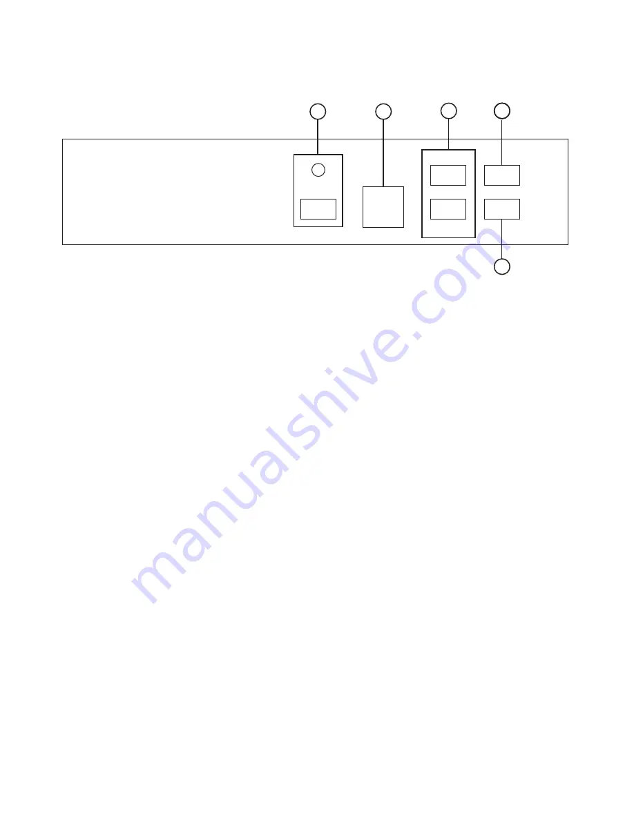
(5). Connecting and Installation
(4). Connecting the hardware
Connecting the Video inputs
The video scaler can accept a composite video, an S-Video or a YCbCr input
signal for scaling, as well as a computer signal input that is passed through the unit
when the PC in (Bypass) is selected.
Rear Panel
1 . Composite Video: Use a Composite video cable to connect the composite video
output of the source equipment to the connector labeled
"C-Video" on the back of the Video Scaler.
2 . S-Video: Use a S-Video cable to connect the S-Video output of the source video
equipment to the connector labled " S-Video" on the back of the
Video Scaler.
S-Video provides improved performance over Composite Video and is
recommended over composite.
3 . YCbCr input: Use a 3 RCA-to-3 RCA YCbCr cable to connect the YCbCr output of
the source video equipment to the connectors labled YCbCr on the
back of the video scaler. Please note the plugs' color have to match
with the color of the RCA Jacks. YCbCr component provides the best
picture quality among all three inputs, and should be used whenever
possible.
4 . Computer RGB with H&V Sync: Connect the source computer's VGA output
signal to the HD 15 connector labled "PC In" on the
back of the Video Scaler.
Note: This Computer inputs signal is not sclaed, but is available for pass-through
when the Video Scaler is in the PC In (Bypass) mode.
Connecting the scaled output to your projector, PDP, or LCD Display
5 . The HD-15 D-Sub connector is shared by PC/RGBHV output and HDTV/YPbPr output.
When PC/RGBHV output resoultion (VGA to SXGA) is selected, use the HD-15 to
HD-15 VGA cable to connect the output to the PC input of your display monitor.
When HDTV/YPbPr output (480p, 576p, 720p, 1080i) is selected, use the HD-15 to
YPbPr 3 x RCA cable to connect the output to the YPbPr input of your HDTV display.
Note: Use of wrong cable for your selected output will result in an abnormal picture
on the screen.
6 . RS232: 9-pin D-sub connector for connecting to your PC or other control console for
remote control.
7 . DC power jack: 5V 2A DC power input.
2
1
3
4
5
7
6
INPUT
S-VIDEO
VIDEO
Y
Cb
Cr
PC IN
RGB/YPbPr
OUTPUT
DC 12V
+
RS 232
DC Adaptor
HDTV
Control In
INPUT
S-VIDEO
VIDEO
Y
Cb
Cr
PC IN
RGB/YPbPr
OUTPUT
DC 12V
+
RS 232
Rear Panel
Содержание CSC-200P
Страница 1: ......
Страница 2: ......
Страница 12: ...Home page http www cypress com tw CYPRESS TECHNOLOGY CO LTD...


