3
with the transmitter’s USB input.
Note:
To activate the link a re-power on is required after each
button pressed.
6
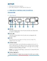
USB In
This slot is to connect with PC/Laptop for input source signal with
USB B type cable.
7
CAT5e/6 Out
This slot is to connect with CAT5e/6 cable with receiver
side’s CAT5e/6 input. When both transmitter and receiver is
connected the green LED will illuminate. When the data is
sending the yellow LED will be blinking.
RECEIVER
6.2 Front Panel
1 2
3
4
5
6
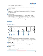
1
USB Link
This LED will illuminate when the transmitter has linked with
receiver’s USB signal. User are only able to control the USB in
(the source device) when this LED is not illuminated.
2
Power LED
This LED will illuminate when the device is plugged with
power supply.
3
DC 5V
Plug the 5V DC power supply into the unit and connect the
adaptor to an AC outlet.

